


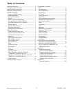

Testing Procedures
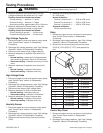
WARNING
!
Disconnect power before performing the following
procedures unless testing requires it.
16021668 Rev. 0 10 ©2002 Maytag Appliances Company
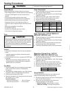
4. Measure resistance of the terminals on the high
voltage transformer with meter on R x 1 scale.
Reading should be indicated as follows:
Primary winding ......less than 1.0 ohms
Filament winding ....less than 1.0 ohms
Secondary winding .approximately 50 to 120 ohms
5. Measure resistance of the terminals on the high
voltage transformer with meter on high scale.
Reading should be indicated as follows:
Primary winding to ground....... Infinite ohms
Filament winding to ground ..... Infinite ohms
High Voltage Capacitor
1. Disconnect power to oven and remove control panel,
(see “Control Panel” section in Disassembly
Procedure).
2. Discharge high voltage capacitor, (see "High Voltage
Capacitor" section in Disassembly Procedure).
3. Disconnect wire leads to high voltage capacitor.
4. Measure resistance of capacitor from terminal to
terminal.
• Normal reading—momentarily indicates several
ohms and then gradually returns to infinite ohms.
• Abnormal reading—Indicates continuity or infinite
ohms.
5. Measure resistance of capacitor from terminal to
case.
• Normal reading—Indicates infinite ohms
• Abnormal reading—Indicates continuity
High Voltage Diode
1. Disconnect power to oven and remove control panel,
(see “Control Panel” section in Disassembly
Procedure).
2. Discharge high voltage capacitor, (see "High Voltage
Capacitor" section in Disassembly Procedure).
3. Disconnect wire leads to high voltage diode.
4. Measure resistance of diode in forward bias.
• Normal reading—Indicates continuity
• Abnormal reading—Indicates infinite ohms
5. Measure resistance of diode in reverse bias.
• Normal reading—Indicates infinite ohms
• Abnormal reading—Indicates continuity
Humidity Sensor
1. Disconnect power to oven and remove control panel,
(see “Control Panel” section in Disassembly
Procedure).
2. Discharge high voltage capacitor, (see "High Voltage
Capacitor" section in Disassembly Procedure).
3. Disconnect wire terminal plug from control board
(CN5).
4. Measure the following terminals with meter on
R x 1000 scale.
Normal indication:
Terminal 1 to terminal 2......... 4.5K to 6.2K ohms
Terminal 2 to terminal 3 ........ 2.0K to 3.5K ohms
Terminal 1 to terminal 3 ........ 2.0K to 3.5K ohms
Abnormal indication:
Infinite or several ohms
Relay
1. Disconnect power to oven and remove control panel,
(see “Control Panel” section in Disassembly
Procedure).
2. Discharge high voltage capacitor, (see "High Voltage
Capacitor" section in Disassembly Procedure).
3. Disconnect wire terminal plug from control board
(ACO18*, RY2) (ACO15*, RY7), and operate the
unit.
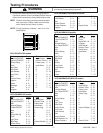
Rela
y2
Power Level Cycles On for: Cycles Off for:
1 4 seconds 18 seconds
2 6 seconds 16 seconds
3 8 seconds 14 seconds
4 10 seconds 12 seconds
5 12 seconds 10 seconds
6 14 seconds 8 seconds
7 16 seconds 6 seconds
8 18 seconds 4 seconds
9 20 seconds 2 seconds
10 22 seconds 0 seconds
Control Key Panel
1. Disconnect power to oven and remove control panel,
(see “Control Panel” section in Disassembly
Procedure).
2. Discharge high voltage capacitor, (see "High Voltage
Capacitor" section in Disassembly Procedure).