


Disassembly Procedures
To avoid the risk of electrical shock, personal injury or
death; disconnect power to oven and discharge
capacitors before following any disassembly procedure.
WARNI NG
!
16021668 Rev. 0 22 ©2002 Maytag Appliances Company
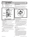
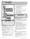
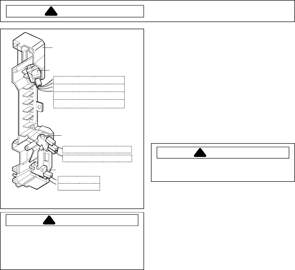
Latch Board
WH (from H.V. Transformer)
YL (from Fan Motor)
WH (from Power Cord)
WH (from Cooktop Lamp)
Secondary Interlock Switch
Monitor Interlock Switch
Primary Interlock Switch
PK (from P.C.B)
BL (from P.C.B)
WH (from H.V. Transforme
r)
RD (from H.V. Transforme
r)
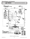
ACO1840*, ACO1860*, JMV8196*,
MMV4184*, and MMV5186*
CAUTION
!
Before replacing a blown monitor fuse, test the
primary interlock switch, secondary interlock switch,
monitor switch, and power relay contacts for proper
operation. If the monitor fuse is blown by a failed
switch operation, all switches and printed circuit board
must be replaced.
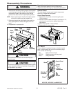
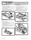
Adjusting Interlocks
The interlock monitor and primary switches act as a final
safety switch, protecting the operator from microwave
energy. After adjusting the interlock switches, verify
connections are correctly connected.
For door fit and switch operation, switch housing is
adjustable.
1. Disconnect power to oven and remove control panel,
(see "Control Panel" procedure).
2. Discharge high voltage capacitor, (see "High Voltage
Capacitor" procedure).
3. Loosen switch housing mounting screws on vertical
flange.
4. Close oven door, move latch board upward toward
the top of the oven and/or away from the door latch
until gaps are less than
1
/64–inch (0.5 mm).
5. Hold latch board securely for proper switch operation
and door fit, retighten screws.
6. Open the oven door slowly, watching the switches.
Verify switches release in the following order.
• Primary interlock switch
• Secondary interlock switch
• Monitor interlock switch
NOTE: Adjust the latch board until all switches operate
in proper sequence.
7. Close the oven door slowly, watching the switches.
Verify switches active in the following order.
• Monitor interlock switch
• Secondary interlock switch
• Primary interlock switch
8. When proper sequence of switch has been achieved,
tighten the latch board securely.
CAUTION
!
A microwave leakage test must be preformed anytime
a door assembly is removed, replaced, disassembled
or adjustment of latch board is made.
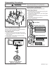
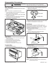
High Voltage Capacitor
High voltage capacitor should always be discharged by
shorting a terminal to a chassis ground. The capacitor
has a internal "shunt" resistor, but the mechanical
discharge should always be performed to avoid personal
injury.
High Voltage Capacitor Removal
1. Disconnect power to oven and remove control panel,
(see "Control Panel" procedure).
2. Discharge high voltage capacitor by connecting a
jumper wire to the terminal of high voltage capacitor
with the diode connected to it. Connect the other
end of the jumper wire to a well insulated
screwdriver and touch a nearby chassis ground
screw.
3. Remove screws that secure capacitor and diode.
4. Slide capacitor mounting bracket out of the slots and
pull outward on capacitor, diode and bracket.
5. Reassemble in reverse order.
Diode
The diode is located next to the high voltage capacitor.
1. Disconnect power to oven and remove control panel,
(see "Control Panel" procedure).
2. Discharge high voltage capacitor, (see "High Voltage
Capacitor" procedure).
3. Disconnect diode wire terminal from high voltage
capacitor and remove screw securing diode to
ground.
4. Reassemble in reverse order.