


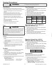

Disassembly Procedures
To avoid the risk of electrical shock, personal injury or
death; disconnect power to oven and discharge
capacitors before following any disassembly procedure.
WARNI NG
!
16021668 Rev. 0 20 ©2002 Maytag Appliances Company
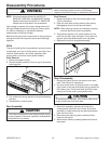
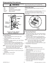
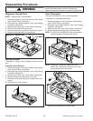
CN1 Main power connector
CN2 Primary switch
CN5 Humidity sensor (some models)
FPC (S1) Ribbon connector for key panel
Relay 2 Relay connector
(CN2)
(CN5)
P
ower
T
ransformer
Relay 2
Control Pan
el
Screw
CN1
Circuit
Board
CN2
CN5
FPC (S-1)
connector
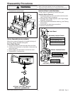
ACO1840*, ACO1860*, JMV8196*,
MMV4184*, and MMV5186*
P.C. Board Removal
1. Disconnect oven power and remove grille, (see
"Grille" procedure).
2. Remove control panel, (see "Control Panel"
procedure).
3. Discharge high voltage capacitor, (see "High Voltage
Capacitor" procedure).
4. Disconnect ribbon connector by sliding top part of
connector upward. Once in released position remove
ribbon from connector by siding ribbon side-to-side.
NOTE: Caution should be used when removing cable
from connector. Ribbon cable has two holes
which connector locks ribbon in place.
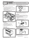
5. Disconnect and mark the wire connectors from p.c.
board.
6. Remove screws securing p.c. board to control panel
assembly.
7. Reassemble in reverse order.
NOTE: Do not flex p.c. board.
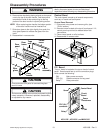
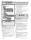
Control Key Panel
The key panel has one ribbon connection on the p.c.
board.
The key panel pads can be checked through a continuity
test. Operations of key pad can be checked by
measuring connections at end of ribbon, (using high
ohms scale).
Plastic
fastener
Holes
Hook
Terminal
socket
F.P.C.
connector
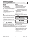
Control Key Panel Removal
1. Disconnect power to oven.
2. Remove control panel, (see "Control Panel" section).
3. Discharge high voltage capacitor, (see "High Voltage
capacitor section).
4. Disconnect ribbon connector by sliding top part of
connector upward. Once in released position remove
ribbon from connector by siding ribbon side-to-side.
NOTE: Caution should be used when removing cable
from connector. Ribbon cable has two holes
which connector locks ribbon in place.
5. Peel failed key pad off and replace with new key pad.
6. Reassemble in reverse order.
Outer Case
NOTE: This procedure requires removal of unit.
1. Disconnect power to oven and remove grille, (see
"Grille" procedure).
2. Remove oven door, (see "Door Removal"
procedure).
3. Remove screws securing air duct to outer case.
4. Remove screws securing outer case to the chassis.
5. Remove screws securing vent plate to outer case.
6. Remove screw securing power cord cover to outer
case and remove power cord cover (if equipped).
7. Slide outer case towards the rear of the unit, guide
power cord though outer case power cord hole.
8. Place outer case to the side, so no damage will
occur to the case.