


Disassembly Procedures
To avoid the risk of electrical shock, personal injury or
death; disconnect power to oven and discharge
capacitors before following any disassembly procedure.
WARNI NG
!
©2002 Maytag Appliances Company 23 16021668 Rev. 0
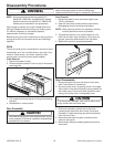
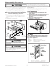
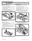
Magnetron
Magnetron is mounted on the side of the cavity to
provide a top feed single waveguide.
1. Disconnect power to oven and remove grille, (see
"Grille" procedure).
2. Remove control panel, (see "Control Panel"
procedure).
NOTE: On the ACO15* and MMV5156* models, remove
the metal protector located above control panel.
3. Remove outer case, (see "Outer Case" procedure).
4. Discharge high voltage capacitor, (see "High Voltage
Capacitor" procedure).
5. Remove screws securing magnetron to the wave
guide.
6. Carefully remove the magnetron.
7. Reassemble in reverse order.
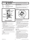
NOTE: When replacing the magnetron, make sure the
gasket is in the correct position and in good
condition.
CAUTION
!
During replacement of magnetron, be certain the R.F.
anode gasket is in place around anode stud.
WARNI NG
!
A microwave leakage test must be performed anytime
a magnetron assembly is removed, replaced,
disassembled or adjusted for any reason.
Magnetron Fan Assembly
Magnetron fan motor provides cool air circulation from
an external air source, which provides direct cool air
through air vanes surrounding the magnetron. This
assembly is located above the magnetron.
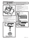
Magnetron Fan Removal
1. Follow steps 1 through 4 of "Magnetron" procedure.
2. Remove fan blade from fan motor.
3. Remove screws securing fan motor to air duct.
4. Disconnect wires from fan motor, and lift fan motor
assembly out.
5. Reassemble in reverse order.
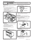
Transformer
High voltage transformer can be serviced through the
front of the unit.
Power Transformer Removal
1. Disconnect power to oven and remove control panel,
(see "Control Panel" procedure).
NOTE: On the ACO15* and MMV5156* models, remove
the metal protector located above control panel.
2. Discharge high voltage capacitor, (see "High Voltage
Capacitor" procedure).
3. Disconnect and label wire leads from transformer.
4. Remove screws securing transformer and remove
out through the front.
5. Reassemble in reverse order.
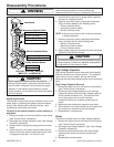
Fuse
On the ACO15* and MMV5156* models the fuse is
located behind the grille in line with the power cord on the
right side of the unit.
On the ACO18*, JMV8196*, MMV4184*, and MMV5186*
models the fuse is located behind the grille on the right
side attached to the air duct.
Fuse Removal
1. Disconnect power and remove grille, (see "Grille
procedure).
2. Remove and replace fuse and reassemble in reverse
order.
CAUTION
!
Before replacing a blown monitor fuse, test the
primary interlock switch, secondary interlock switch,
monitor switch, and power relay contacts for proper
operation. If the monitor fuse is blown by a failed
switch operation, all switches and printed circuit board
must be replaced.