


Disassembly Procedures
To avoid the risk of electrical shock, personal injury or
death; disconnect power to oven and discharge
capacitors before following any disassembly procedure.
WARNI NG
!
©2002 Maytag Appliances Company 21 16021668 Rev. 0
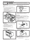
9. Reassemble in reverse order.
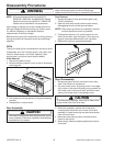
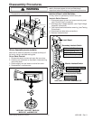
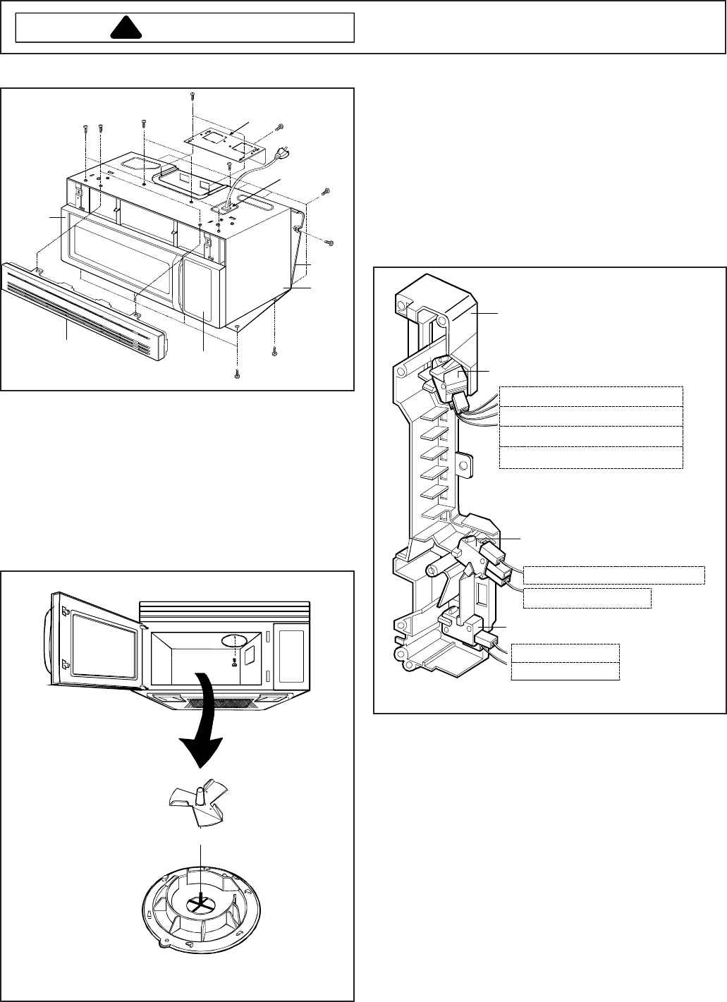
Vent grille
Controller
Mounting
plate
Door
Outter cas
e
Vent plate
Power cord cover
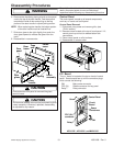
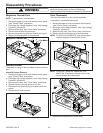
Stirrer Assembly (some models)
Motor driven antenna assembly is located at the top of
the cavity, using a top feed wave guide.
Stirrer Blade Removal
1. Disconnect power to oven and open the oven door.
2. Carefully pry downward on the plastic rivets securing
the stirrer cover.
3. Rotate slightly and pull down on stirrer fan cover .
4. Reassemble in reverse order.
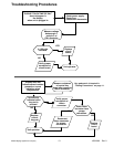
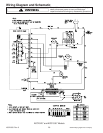
ACO1840*, ACO1860*, JMV8196*,
MMV4184*, and MMV5186*
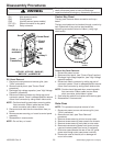
Interlock Door Latch Switches
Primary switch is operated by bottom latch pawl.
Interlock Switch Removal
1. Disconnect power to oven and remove control panel,
(see "Control Panel" procedure).
2. Discharge high voltage capacitor, (see "High Voltage
Capacitor" procedure).
3. Test interlock switches before removing, (see Testing
Procedures).
4. Disconnect and label wire connections.
5. Remove interlock switch.
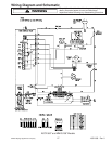
Latch Board
WH (from H.V. Transformer)
WH (from Monitor S/W)
WH (from Oven Thermostat)
WH (from Cooktop Lamp)
Secondary Interlock Switch
Monitor Interlock Switch
Primary Interlock Switch
GN (from P.C.B)
YL (from P.C.B)
WH (from Secondary switch
)
RD (from Relay 7)
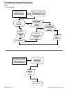
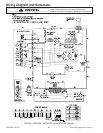
ACO15020*, ACO1530*, and MMV5156*