


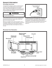
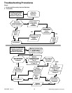
Testing Procedures
WARNING
!
Disconnect power before performing the following
procedures unless testing requires it.
16021668 Rev. 0 12 ©2002 Maytag Appliances Company
Circuit Board
Following symptoms indicate a failed circuit board.
• High voltage systems, interlock switches, door sensing
and relay indicate good, but start function fails to
operate.
• Continuously operating with a normal relay.
• Proper temperature measurement is not obtained.
• Buzzer does not sound or sounds continuous.
• Segments of one or more digits do not light, or
continue to light or segments light when they should
not.
• Wrong figures appear in the display.
• All segments light up.
• Some of the indicators light up or flicker.
• Clock does not keep time properly.
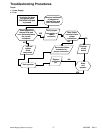
Fuse
CAUTION
!
Before replacing a blown monitor fuse, test the primary
interlock switch, secondary interlock switch, monitor
switch, and power relay contacts for proper operation.
If the monitor fuse is blown by a failed switch
operation, all switches and printed circuit board must
be replaced.
Problem:
• Fuse blows immediately after oven door is opened or
closed.
• Improper operation of primary, secondary and/or
monitor switches.
• Fuse blows when oven door is closed and START pad
is pressed.
• Malfunction of the high voltage transformer, high
voltage capacitor including the diode, magnetron,
blower motor or circuit board.
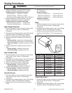
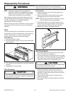
Fan Motor
1. Disconnect power to oven and remove control panel,
(see “Control Panel” section in Disassembly
Procedure).
2. Discharge high voltage capacitor, (see "High Voltage
Capacitor" section in Disassembly Procedure).
3. Disconnect wire leads to fan motor.
4. Measure resistance of the terminals on the fan motor
with meter on R x 1 scale.
Normal indication:
Terminal A to terminal C ........ 140 to 150 ohms
Terminal A to terminal B ........ 25 to 40 ohms
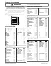
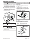
Oven Thermostat
1. Disconnect power to oven and remove control panel,
(see "Control Panel" section).
2. Discharge high voltage capacitor, (see "High Voltage
Capacitor" section).
3. Remove outer case, (see "Outer Case" section).
4. Lift air duct securing thermostat to oven cavity.
5. Disconnect wires from oven thermostat.
6. Following is temperature setting for the thermostat.
Model Fahrenheit Centigrade Cycle
ACO15*
194°F90°C
OFF
MMV5156*
32°F0°C
ON
ACO18*
MMV4184*
230°F110°C
OFF
MMV5186*
JMV8196*
32°F0°C
ON
Base Thermostat – ACO18*/MMV4184*/
MMV5186*/JMV8196* only
1. Disconnect power to oven and remove control panel,
(see "Control Panel" section).
2. Discharge high voltage capacitor, (see "High Voltage
Capacitor" section).
3. Remove screws securing thermostat to base plate
and disconnect wires from thermostat.
4. Following is temperature setting for the thermostat.
Magnetron Thermal Fuse – ACO18*/
MMV4184*/MMV5186*/JMV8196* only
1. Disconnect power to oven and remove control panel,
(see "Control Panel" section).
2. Discharge high voltage capacitor, (see "High Voltage
Capacitor" section).
3. Remove outer case, (see "Outer Case" section).
4. Remove screws securing thermal fuse to fan motor.
5. Disconnect wires from magnetron thermal fuse.
6. Following is temperature setting for the thermostat.
Fahrenheit Centigrade
228
°
F109
°
C
Surge Resistor
This resistor prevents the oven from tripping circuit
breakers and blowing fuses during start up.
1. Disconnect power to oven and remove control panel,
(see "Control Panel" section).
2. Disconnect wire terminals to the resistor and
measure resistance of the resistor.
• Normal reading—approximately 15 ohms.
• Abnormal reading—Indicates infinite ohms.