


WARNI NG
!
To avoid risk of electrical shock, personal injury, or
death, disconnect power to unit before servicing.
Disassembly Procedures
16 16021875 Rev. 0 ©2003 Maytag Appliances Company
WARNING
!
To avoid risk of personal injury or property damage
this unit requires a two man lift when lifting unit in or
out of cutout.
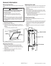
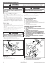
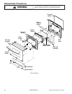
Removing and Replacing Oven
1. Turn off power to the oven at the circuit breaker.
2. Open oven door and remove screws securing unit to
the wall.
3. Pull the oven forward out of the cabinet opening.
4. Disconnect or unplug the power cord leading from
unit to fuse box or junction box depending on unit.
5. Replace the oven using the installation instructions.
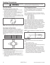
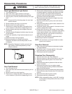
Control Panel
1. Turn off power to unit.
2. Open oven door and remove screws securing unit to
the wall.
3. Slide unit approximately 6 inches out of wall cutout.
4. Remove screws securing control panel to unit,
located on the outer portion of trim.
5. Gently pull control panel forward to gain access to
wire terminals.
WARNING
!
While unplugging electrical connections, pins may be
damaged, use extreme care when disconnecting.
6. Disconnect and label wire terminals.
7. Reverse procedure to reinstall control panel.
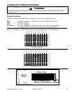
Control
panel
assembly
Electrical
insulator
ERC/P.C. Board
1. Turn off power to unit.
2. See “Control Panel” for removal.
WARNI NG
!
While unplugging electrical connections, pins may be
damaged, use extreme care when disconnecting.
3. Disconnect all electrical connection from E.R.C. unit.
4. Remove screws securing E.R.C. to control glass
panel.
5. Reverse procedure to reinstall E.R.C..
Transformer/Relay Board
1. Turn power off to unit.
2. See “Control Panel” for removal.
3. Disconnect and label wire terminals.
4. Release plastic tabs securing circuit board to control
glass panel.
5. Reverse procedure to reinstall.
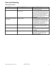
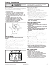
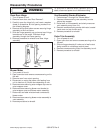
Oven High Limit/Fan Control Switch
1. Turn power off to unit.
2. Open oven door and remove screws securing unit to
the wall.
3. Remove oven from cutout opening.
4. Disconnect or unplug the power cord leading from
unit to fuse box or junction box depending on unit.
5. Remove screws securing outer wrapper top cover to
outer wrapper cover.
6. Disconnect and label wire terminals connected to
limit switch.
F
ront of Unit
Blower
motor
Blowe
r
moto
r
brack
et
Oven
high
limit
Fan
control
switch
7. Remove screws securing high limit switch.
8. Reverse procedure to reinstall switches.