


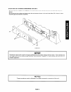
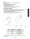

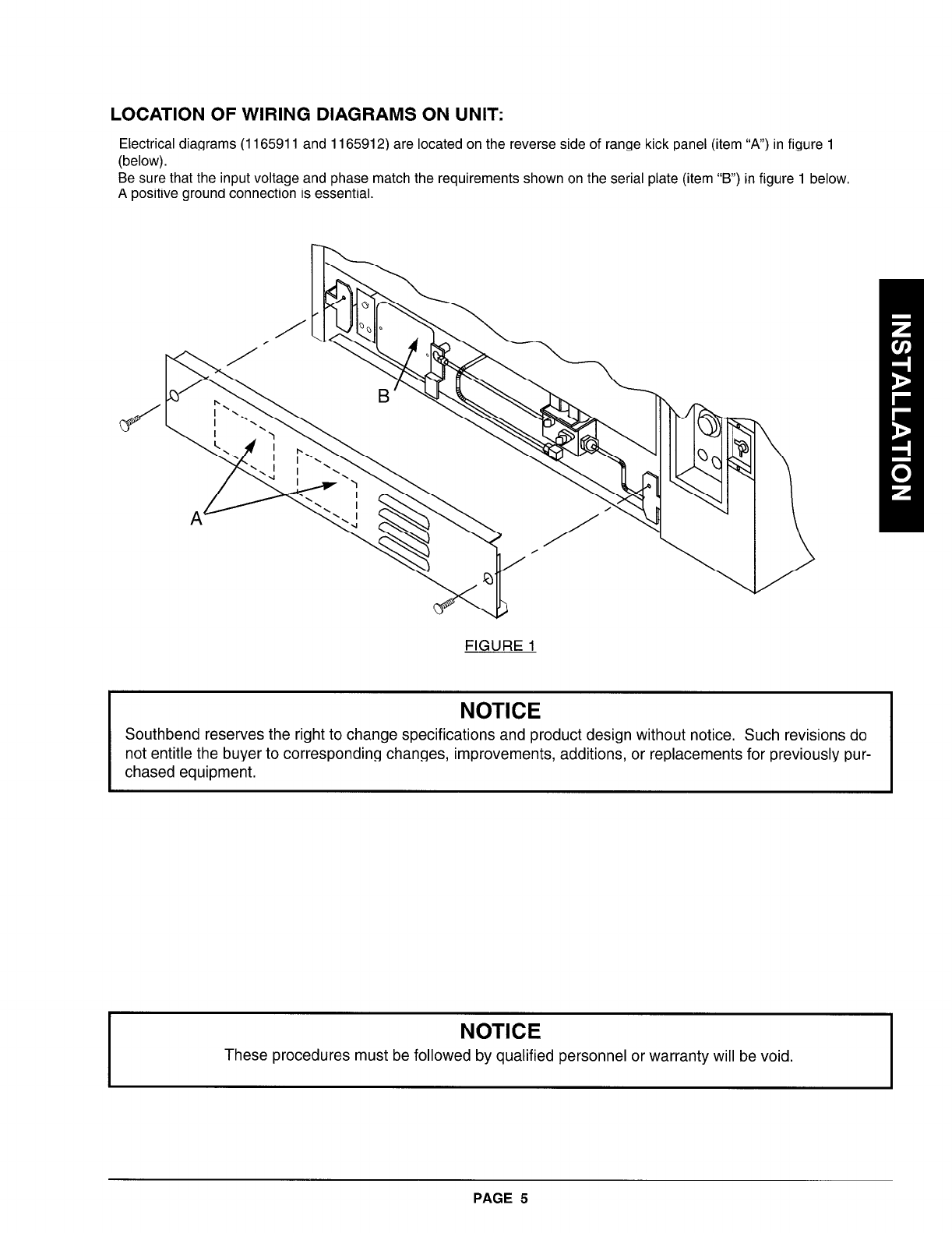
LOCATION OF WIRING DIAGRAMS ON UNIT:
Electrical diagrams (1165911 and 1165912) are located on the reverse side of range kick panel (item “A”) in figure 1
(below).
Be sure that the input voltage and phase match the requirements shown on the serial plate (item “B”) in figure 1 below.
A positive ground connection is essential.
FIGURE 1
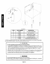
NOTICE
Southbend reserves the right to change specifications and product design without notice. Such revisions do
not entitle the buyer to corresponding changes, improvements, additions, or replacements for previously pur-
chased equipment.
NOTICE
These procedures must be followed by qualified personnel or warranty will be void.
PAGE 5