


GENERAL:
NOTICE
The unit, when installed, must conform with local codes, or in the absence of local codes, with the
National Fuel Gas Code, ANSI Z223.1-latest edition, Natural Gas Installation Code, CAN/CGA-B149.1
or the Propane Installation Code, CAN/CGA-B149.2, as applicable.
The unit, when installed, must be electrically grounded and comply with local codes, or in the
absence of local codes, with the National Electrical Code ANSVNFPA 70-latest edition, or the
Canadian Electrical Code, CSA C22.2, as applicable.
Canadian installation must comply with CAN/CGA-B149.1 natural gas installation code, code
CAN/CGA-B149.2 propane installation code, and CSA C22.1 Canadian electrical code, parts I
or local codes.
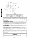
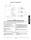
GAS CONNECTION:
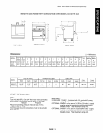
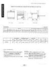
The Serial Plate is located inside unit behind kick panel item “B” on figure 1. It indicates the type of gas the unit is
equipped to burn. All Southbend equipment is adjusted at the factory. Check type of gas on serial plate.
These models are design-certified for operation on natural or propane gases. For natural gas, the regulator is set to
deliver a 4” W.C. pressure to the manifold. For propane gas, it is set to deliver IO” W.C.
This appliance should be connected ONLY to the type of gas for which it is equipped.
An adequate gas supply is imperative. Undersized or low pressure lines will restrict the volume of gas required for satis-
factory performance. Fluctuations of more than 25% on natural gas or 10% on propane gas will create problems and
affect burner operating characteristics. A l/8” pressure tap is located on the manifold to measure the manifold pressure.
An adequate gas supply line to the unit should be no smaller than the I.D. of the pipe from the unit to which it is connect-
ed.
Purge the supply line to clean out dust, dirt, or other foreign matter before connecting the line to the unit.
All pipe joints and connections must be tested thoroughly for gas leaks. Use only soapy water for testing on all gases.
NEVER use an open flame to check for gas leaks. All connections must be checked for leaks after the unit has been
put into operation. Test pressure should not exceed i/4” W.C.
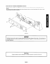
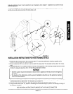
Unit equipped with factory installed certified gas quick-disconnect device. Reference additional installation required for
restraining device, see figure 5 of this document.
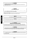
A WARNING
This appliance and its individual shut-off valve must be disconnected from the gas supply piping
system during any pressure testing of the system at test pressures in excess of l/2 PSIG (3.45 KPa).
This appliance must be isolated from the gas supply piping system by closing its individual manual
shutoff valve during any pressure testing of the gas supply piping system at test pressure equal to or
less
than l/2 PSIG 93.45 KPa.
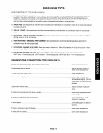
If this equipment is being installed at over 2,000 feet altitude and was not specified on order, contact the appropriate
authorized Southbend Service Representative or the Southbend Service Department. Failure to install with proper
orifice sizing will result in improper performance and may void the warranty.
PAGE 6