


NOTICE
If applicable, the vent line from the gas appliance pressure regulator shall be installed to the outdoors in
accordance with local codes, or in the absence of local codes, with the National Fuel Gas Code, ANSI
2223.1, Natural Gas Installation Code, CAN/CGA-B149.1, or the Propane Installation Code, CANKGA-
B149,2, as applicable.
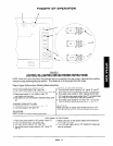
ELECTRICAL CONNECTIONS: (Convection-Type Ovens)
A. 115V - 60 HZ - SINGLE PHASE
Ovens with this electrical rating are factory supplied with three-wire cord and three-prong plug which fits any
standard three-prong grounded receptacle.
Single oven base units require one 15 amp supply.
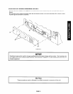
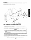
B. 208/236V - 60 HZ - SINGLE OR THREE PHASE
Ovens with this electrical rating are factory equipped with a 2-pole terminal block located behind a cover plate
(single oven range units) and the blower box side cover (double oven base range units) located at the rear of
the unit. To connect the supply wires, remove the appropriate cover plate. Route the supply wires and the
grounding wire through the strain relief fitting to the terminal block. Insert the supply wires, one each, into the two
poles of the terminal block and tighten the screws. Insert the ground wire into the grounding lug and tighten the
screw. Re-attach the cover plate.
Three phase units are wired as above, using only two supply wires. The third wire is not used and must be
properly terminated.
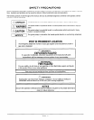
h!!, WARNING
IMPROPER GROUNDING COULD RESULT IN ELECTRICAL SHOCK
This appliance is equipped with a three-prong (grounded) plug for your protection against shock hazard
and should be plugged directly into a properly grounded three-prong receptacle. Do not cut or remove
the grounding prong from this plug.
THREE PHASE TO SINGLE PHASE CONVERSION:
All units are shipped wired as specified by factory order. Conversion between single/three phase can be accomplished
by referring to phase loading and line amperes chart on wiring diagram for wire size and amp requirements.
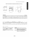
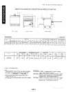
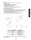
CLEARANCES:
Minimum Clearances -- Inches (mm)
From Combustible
From Non-Combustible
Construction Construction
Back
0 inches
Right Side
8 inches
Left Side
8 inches
Suitable for installation on combustible floors.
0 inches
0 inches
0 inches
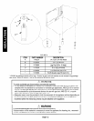
All units must be installed in such a manner that the flow of combustion and ventilation air are not obstructed.
Provisions for an adequate air supply must be provided. Do not obstruct the front or rear of the unit, as combustion
air enters through this area.
manufacturer’s instructions.
Be sure to inspect and clean the ventilation system according to the ventilation equipment
No additional clearance from the sides and back is required for service as the units are serviceable from the front.
Adequate clearance must be provided in the aisle and at the side and rear to allow the door to open sufficiently to
permit the removal of the racks and for serviceability.
Clearance for proper air circulation for motor should be 2” minimum from wall.
PAGE 7