


38
RLC-PRC005-E4
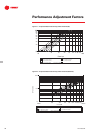
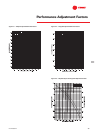
Controls
Safety Controls
A centralized microcomputer offers a
higher level of machine protection.
Because the safety controls are smarter,
they limit compressor operation in order
to avoid compressor or evaporator
failures, thereby minimizing nuisance
shutdowns. Tracer
™
Chiller Controls
directly senses the control variables that
govern the operation of the chiller:
motor current draw, evaporator
pressure, condenser pressure, and so
forth. When any one of these variables
approaches a limit condition at which
the unit may be damaged or shut down
on a safety, Tracer Chiller Controls takes
corrective action to avoid shutdown and
keep the chiller operating. It does this
through combined actions of
compressor slide-valve modulation,
electronic expansion-valve modulation,
and fan staging. Tracer Chiller Controls
optimizes total chiller power
consumption during normal operating
conditions. During abnormal operating
Tracer
™
Chiller Control human interfaces
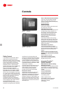
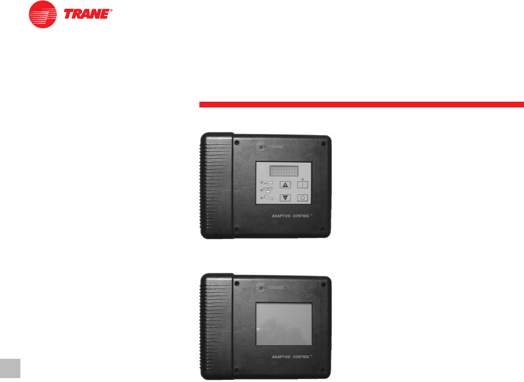
The Trane air-cooled Series R Model
RTAC chiller offers two easy-to-use
operator interface panels, the EasyView,
and the DynaView.
Standard Features
External Auto/Stop
A job-site-provided contact closure will
turn the unit on and off.
Chilled Waterflow Interlock
A job-site-provided contact closure from
a chilled-water pump contactor, or a
flow switch, is required and will allow
unit operation if a load exists. This
feature will allow the unit to run in
conjunction with the pump system.
External Interlock
A job-site-provided contact opening
wired to this input will turn the unit off
and require a manual reset of the unit
microcomputer. This closure is typically
triggered by a job-site-provided system
such as a fire alarm.
Chilled Water Pump Control
Unit controls provide an output to
control the chilled-water pump(s). One
contact closure to the chiller is all that is
required to initiate the chilled-water
system.
Additional Features That May Be Used
(requires some optional factory-installed
hardware)
Alarm Indication Contacts
Chilled-Water Temperature Reset
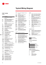
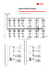
Note: All wiring outside the unit is
supplied at the job site.
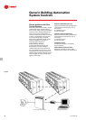
Integrated Comfort™
System Interface
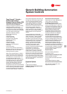
Easy Interface to a Generic Building
Management System
Controlling the air-cooled Series R chiller
with building management systems is
state-of-the-art, yet simple. Chiller inputs
include:
• Chiller enable/disable
• Circuit enable/disable
• Chilled liquid set point
• Current limit set point
• Ice-making enable
Chiller outputs include:
• Compressor running indication
• Alarm indication (ckt 1/ckt 2)
• Maximum capacity
• Ice making
conditions, the microprocessor will
continue to optimize chiller performance
by taking the corrective action necessary
to avoid shutdown. This keeps cooling
capacity available until the problem can
be solved. Whenever possible, the chiller
is allowed to perform its function: make
chilled water. In addition,
microcomputer controls allow for more
types of protection, such as over and
under voltage! Overall, the safety
controls help keep the building or
process running and out of trouble.
Stand-alone controls
Interfacing to stand-alone units is very
simple: only a remote auto/stop for
scheduling is required for unit operation.
Signals from the chilled-water pump
contactor auxiliary, or a flow switch, are
wired to the chilled-water flow interlock.
Signals from a time clock or some other
remote device are wired to the external
auto/stop input.
Figure 7 — Easy View
Figure 8 — Dyna View