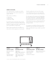
THE CONTROL SYSTEM
14
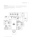
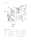
CONTROL SYSTEM COMPONENT DESCRIPTIONS
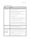
24 VDC Power Supply
24 VDC output at 40 watts. Supplies control
voltage for I/O control board, 24 VDC mechanical
relays, and solid state relays.
K1 Mechanical Relay
240 VAC, 30 Amp, Double Pole, Double Throw, 24
VDC Relay Coil. Switches power to the magnetron
filament transformers.
K2 Mechanical Relay
240 VAC, 30 Amp, Double Pole, Double Throw, 24
VDC Relay Coil. Switches power to the magnetron
high voltage transformers.
K3 Mechanical Relay
240 VAC, 30 Amp, Double Pole, Double Throw, 24
VDC Relay Coil. Safety interlock device designed to
short L1 and L2 if the monitor switch opens before
the primary or secondary interlock switches.
K4/K5 SSR
240 VAC, Dual 40 Amp Solid State Relay. K4
(right) controls the convection heater and K5 (left)
controls the IR element.
K6 Mechanical Relay (North America Only)
240 VAC, 30 Amp, Three Pole, Double Throw, 24
VDC Relay Coil. Responsible for switching between
the 208VAC and 240VAC taps on the high volt-
age and filament transformers.
K7 Relay
24 VDC, 20 Amp, Sealed. Starts with command
from I/O board; switches magnetron cooling fan on
and off. Timer for switching off mag fan is 4:15
after filament switches off.
Interlock Switches
Primary, Secondary, and Monitor Interlock Switches .
Must be actuated by the oven door. When the door
opens, the order is: P, S, M.
IR Thermocouple
Type K Thermocouple. Embedded in the IR ele-
ment, the IR thermocouple measures the inter-
nal/sheath temperature of the IR element. Valid IR
set points are between 500
º
F (260
º
C) and 1150
º
F
(621
º
C). The display indicates 1999
º
F/C if the
thermocouple is “open”.
EC Thermocouple (P/N 700-1199)
Type K Thermocouple. Thermocouple measures the
temperature of the electrical compartment. If the
temperature within the electrical compartment is
above 158
º
F (70
º
C), the control displays
F6: EC
TEMP
. The control board checks the EC tempera-
ture every 60 seconds.
CC Thermocouple
Type K Thermocouple. Thermocouple measures
the temperature of the re-circulating impingement
airflow. Valid CC set points vary depending on
software. If the display indicates 999
º
F/C, the ther-
mocouple is “open.”
BMSC
Proprietary Brushless DC Motor Controller.
Designed solely to operate the blower motor.
VFD (Display)
Vacuum Fluorescent Display.
Keypad
5x9 Matrix Membrane Switch. Keypad is connected
to the I/O control board via 14-pin flat cable.
Voltage Sensor (North America Only)
Proprietary device designed to measure incoming
line voltage and switch between 208 and 240 VAC
operation. The device measures and allows the user
to configure the oven only when the oven is first
powered on. Voltage sensor will default at 240
VAC.
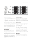
TEST MODE
The Test Mode allows the service technician to
operate the oven’s subsystems individually. It also
allows the operator to configure various presets.


