


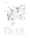
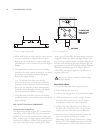

MICROWAVE SYSTEM COMPONENTS
Below is a description of each component within
the Microwave System.
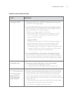
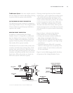
Magnetron
Magnetrons supply the RF energy at 2.45 GHz
and begin to oscillate when they are supplied with
approximately 4.1KVDC at approximately .350 mA.
During operation each magnetron will output a
nominal 1 kW of power.
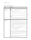
High-Voltage Transformers
High-voltage transformers are a ferro-resonant
design which limits fault currents and minimizes
magnetron power changes due to input voltage
changes. The high-voltage transformer supplies
the high voltage for the Voltage Doubler Circuit.
They are controlled via the K2 relay.
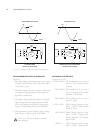
WARNING: Never attempt to measure
the voltage values of the high-voltage trans-
formers with the high-voltage transformers enabled.
Lethal voltage will be present. Reference page 30
for proper measuring technique.
Filament Transformers
For better operation and reliability, the oven
uses separate transformers in order to preheat the
magnetron filament.
The control energizes the filament transformers for
approximately five (5) seconds prior to energizing
the Microwave Circuit via the high-voltage trans-
formers. When in operation, the filament trans-
formers supply approximately 3.15 VAC at 10 amps
to each magnetron filament. The filament trans-
formers are controlled via the K1 relay.
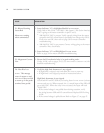
F3 Fuse
The F3 fuse is a 20-amp, class CC fuse designed to
blow in case of an over-current scenario, such as a
high-voltage transformer or capacitor failure. The
fuse also blows if the Monitor Circuit trips the
failsafe.
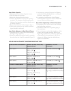
High Voltage Capacitors
Capacitor rating is 0.91uF, 2500 VDC for USA,
Mexico, Brazil, and S. Korea.
Capacitor rating is 1.15 uF, 2500 VDC for
Europe, Asia, Pacific, Australia, UK, Ireland, and
Japan 50 Hz.
Capacitor rating is 0.85 uF, 2500 VDC for Japan
60 Hz.
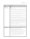
High Voltage Diodes
Rated at 16 kVDC.
Monitor Relay (K3)
The monitor relay, K3, acts as a failsafe device in
the Voltage Doubler Circuit. In its normal un-ener-
gized position, the monitor relay shorts L1 and L2.
If the K2 relay energizes the high-voltage trans-
formers while the K3 relay is un-energized, the F3
fuse will blow.
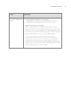
Magnetron Thermostats
The magnetron thermostats are open-on-rise ther-
mostats. These thermostats are designed to open at
212
º
F (100
º
C), which triggers an F5 fault.
NOTE: Both magnetron thermostats are wired
in series. If one opens, the control will switch off
both magnetrons until the thermostats close. The
thermostats are self-resetting.
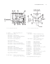
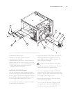
Magnetron Cooling Fan
The magnetron cooling fan supplies cooling air for
both magnetrons. The fan operates at 208 or 240
(USA) / 230 (Intl) / 200 (Japan) / 220 (Latin
America) VAC and is controlled via the K7 relay
(see Item 14 on Figure 20).
If the oven does not have this relay installed, it is
required that you order the relay kit through
Customer Service. See page 27, item 14 for part
numbers. If you are unsure which kit to order,
determine the software type before contacting
Customer Service.
THE MICROWAVE SYSTEM
28