THE MICROWAVE SYSTEM
25
The Microwave System is the most complex system in
the oven. Proper care must be taken during servicing
to protect both the operator and technician.
VOLTAGE DOUBLER CIRCUIT DESCRIPTION
The Microwave System consists of a magnetron
and Voltage Doubler Circuit. The Voltage Doubler
Circuit consists of a special step-up transformer, a
capacitor, and a diode.
MONITOR CIRCUIT DESCRIPTION
In addition to understanding the Voltage
Doubler Circuit, it is imperative to understand
how the Monitor Circuit operates. The Monitor
Circuit is a failsafe circuit designed to protect the
operator if both the primary and secondary inter-
lock switches fail to operate normally.
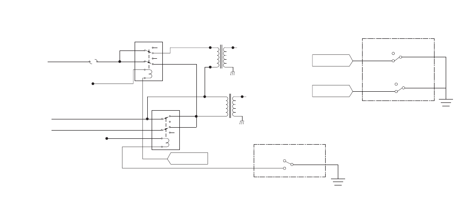
The Monitor Circuit consists of the primary and
secondary interlock switch, monitor safety switch,
monitor relay, and the F3 fuse. When the oven
door closes during normal operation, the monitor,
secondary, and primary switches close in the order
listed above. When all switches are closed, the
Microwave System is allowed to operate.
If during normal operation any of the interlock
switches open - such as when the oven door opens
- the control will turn off the microwave. If the
monitor switch opens before the primary or sec-
ondary switches (abnormal operation), the monitor
switch de-energizes the monitor relay. When this
occurs, a dead short is placed across L1 and L2.
The short then blows the F3 fuse, which perma-
nently interrupts power to the Microwave System
until all switches are repaired and/or functioning
properly.
Figure 18 shows a schematic of the Monitor
Circuit. Make sure to note the following:
Primary and secondary switches interlock the
high-voltage control signal. (K2 relay)
Normal operation: When the K2 and K3 relays
energize, power is supplied to the high-voltage
transformers.
Abnormal operation: When K2 is energized
and K3 is un-energized (via an opening of the
monitor switch), L1 and L2 short to blow the
F3 fuse and failsafe.
Figure 19 on the following page details the theory
of operation of the Voltage Doubler Circuit.
