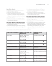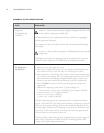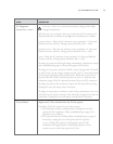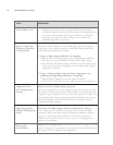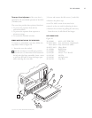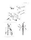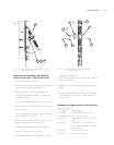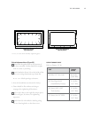
FIGURE
29: Correct Primary and Secondary Interlock
Adjustment and Parts - Old Switch Setup
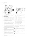
DOOR SWITCH ASSEMBLY AND PARTS
Figure 30, next page
53. NGC-1072 Bracket Latch
54.102012 Switch, Micro, 0.1A/125VAC
55. NGC-1087 Spring Door Latch
56. NGC-1073 Toggle, Latch
57. 101119 Pin, Clevis, ø3/16 x 1” Lg
58. 100059 Bearings, Bronze,
3/16ID x 5/16OD x 1/4” Lg
59. 101557 Screw, #4-40 x 1.25” Lg,
PPHD, CRES
60. 102921 Screw, #8-32 x 3/8”, Internal
Tooth Sems, PPHD, SS
61. NGC-1126 Plate, Door Switch
62. NGC-3006 Grease, USDA H-1, Food Grade
63. 101296 Ring, E-clip
Assembly Notes
1. Ring, e-clip (Item 63) is supplied with Item 56.
2. Spring and bracket must be lubricated with high-
temperature pure FM grease (Item 62).
3. Assembly must be hand-tightened prior to any
final adjustment.
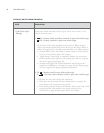
ADJUSTING THE MONITOR SWITCH - OLD SETUP
The old switch assembly is identifiable by the moni-
tor switch being located on the right hinge assembly.
Also, the serial number of the oven will follow this
formatting (X = variable digit/letter):
NGC-XXXXX (North America)
NGCXX-XXXXX (International)
To adjust the switch, follow the steps below.
1. Ensure the oven door is adjusted. Refer to
ADJUST-
ING THE COOK DOOR
on page 38.
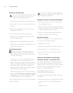
2. Turn on oven and bring it to the set temperature.
WARNING: Oven surfaces are HOT! Use
extreme caution when making adjustments.
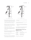
3. Open and close the oven door several times to
ensure the door closes smoothly and the door
actuator (Item 47) clears the slot in the flange.
Reference Figure 29.
4. Disconnect oven from power source.
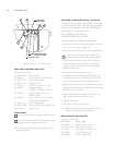
5. To adjust the monitor safety switch (Figure 31),
loosen the #8-32 screw and the two (2) #4-40
screws (Items 68 and 69) securing the switch.
6. Rotate the monitor safety switch (Item 65) until
the gap between the switch paddle and the switch
body is 0.02” (0.5 mm).
7. Open and close the oven door several times to
make certain the adjustment is correct.
8. Tighten all screws.
9. Reconnect oven to power source.
10. Allow oven to sit at the set temperature for 10
minutes and confirm all adjustments.
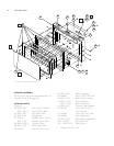
MONITOR SAFETY SWITCH PARTS
Figure 31, next page
64. 102804 Hinge, Right
65. 102012 Switch, Limit, Micro
66. NGC-1126 Plate, Door Switch
67. 101912 Standoff, #8-32F/Fx1 in S
68. 102921 Screw, #8-32 x 3/8”
69. 102902 Screw, 4-40 x 5/8”
SWITCH GAP
= 0.020”
4950
51
52
TOGGLE SHOULD BE LESS THAN
OR EQUAL TO
85
º
DOWN
APPLY HI
-TEMP
GREASE TO AREA
48
47
THE OVEN DOOR
40


