high-voltage transformers are most likely wired in-
phase. As a last check, energize the Microwave
System and verify the voltages between the taps on
each high-voltage transformer. The wiring issue
must be corrected prior to returning the oven to
service, as the voltages must be:
NORTH AMERICA: 208 VAC between 1&2and
240 between 1&3.
LATIN AMERICA: 220 VAC
JAPAN: 200 VAC
INTERNATIONAL: 230 VAC
NOTE
: The terminals with the orange dot or
the orange wire always go to terminal
3 on USA
models
.
Wiring the Filament Transformers
The installation of filament transformers is
straightforward. Filament transformers are wired
in-phase and in-line. Refer to the schematics on
pages 55-63, detailing the proper wiring.
Specifically, FT1 and FT2 are located in the
middle-far right edge of the schematics.
To verify correct wiring (North America), meas-
ure the voltages between terminals
1&2and 1&3
on FT1 and FT2. The voltages must be 208 and
240 VAC respectively.
NOTE
: The terminals with the orange dot or the
orange wire always go to Terminal
3 on US models.
To verify correct wiring (International), measure the
voltage between the taps on FT1 and FT2. The volt-
age must be 220 VAC (Latin America), 200 VAC
(Japan), or 230 VAC (International).
MEASURING RF LEAKAGE FOR MICROWAVE SAFETY
An RF (microwave) leakage test must be performed
at the conclusion of the following service tasks:
Door removal, replacement and/or adjustment
Wave guide removal and/or replacement
Magnetron removal and/or replacement
WARNING: If the unit fails the radiation
test (leakage greater than 4 mW/cm
2
), the
oven must be taken out of service immediately until
the defect is corrected. In addition, the CDRH
Regulations 21 Subpart C, 1002.20 requires that
leakage readings of over 4 mW/cm
2
must be
reported to the manufacturer.
Procedure for Measuring RF Leakage
1. Place the oven in
WARM UP and allow it to warm
up to the set temperature (CCSP). This should
take approximately 13 minutes if the oven is
starting out cold.
2. Once the oven has warmed up, place the oven
into
TEST MODE (see page 14). Place a water
load into the cook cavity. Water load must con-
form to the following specification:
a. Volume: 275ml ± 15ml
b. Temperature: 68 ± 9
º
F (20 ± 5
º
C)
c. Vessel: Low form, 600 ml beaker with an
inside diameter of approximately 3.35” (85
mm) and made of Pyrex or glass ceramic.
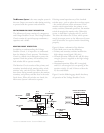
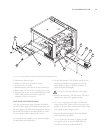
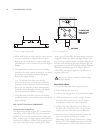
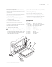
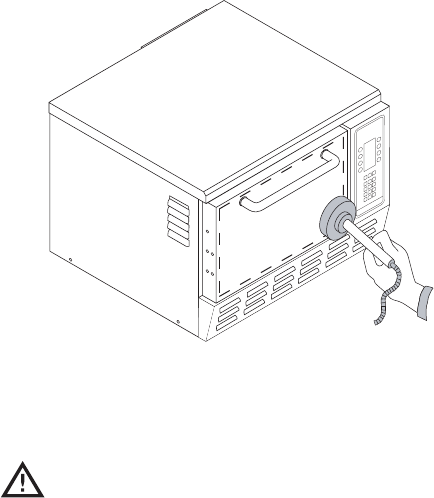
3. Position the microwave survey meter as shown
in Figure 23.
4. Press and hold the
MGTRON soft key to energize
the Microwave System.
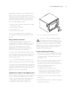
FIGURE 23: Microwave Survey Meter Placement
31
THE MICROWAVE SYSTEM


