


THE MICROWAVE SYSTEM
32
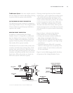
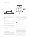
5. While holding the MGTRON soft key, move the sur-
vey meter around the outline of the oven door,
keeping the tip of the meter in contact with and
perpendicular to the oven door. Record the highest
leakage.
6. Using the same procedure, measure the leakage
with the oven door opened to the point just before
the primary and secondary switches disengage.
Record the highest leakage.
TIP: To hold the oven door open for this
test, back out the top center screw around the
perimeter of the oven door. Continue backing
this screw out until the primary and secondary
interlock switches disengage. As this point, tighten
the screw until both switches re-engage.
7. Using the same procedure, measure the leakage
around the oven’s entire exterior surface. Record the
highest leakage.
HOW TO TEST MICROWAVE COMPONENTS
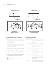
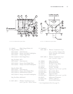
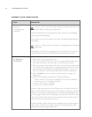
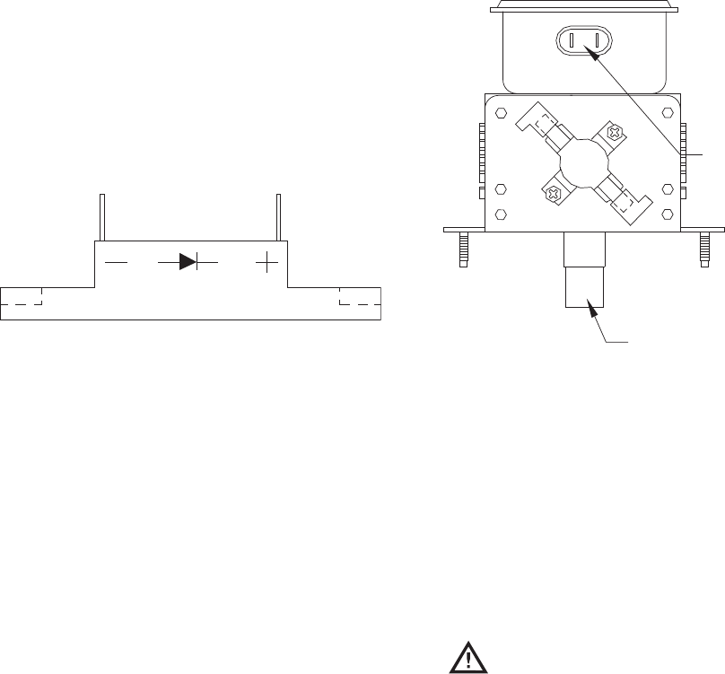
Testing the High-Voltage Diode
The high-voltage diode (Figure 24) is assembled by
connecting several 1000-1500 volt semiconductor
diodes in a series to increase the reverse voltage capa-
bility. In the circuit, the high-voltage diode conducts
to prevent the filament voltage from becoming posi-
tive, thus as the high-voltage winding of the trans-
former goes to 2400 VPK, the high-voltage capacitor is
charged to 2400 volts. When the high-voltage wind-
ing starts to go toward negative, the high-voltage diode
becomes non-conducting with the charged high-volt-
age capacitor in series with the high-voltage winding.
When the transformer gets to its negative peak of
-2400 VPK, the voltage applied to the filament is
negative 4500 volts.
WARNING: Never attempt to measure high
voltage directly.
How to Check a Diode
1. Disconnect the oven from the power source.
2. Fully discharge the capacitors.
3. Connect the voltage meter in series with the diode.
4. Using a multimeter set to DC voltage, connect
one meter lead to one side of a 9-volt battery
and the other lead to one side of the diode.
5. Connect the other side of the 9-volt battery to
the other side of the diode. DC voltage should
only be present on the meter in one direction.
6. Switch the meter leads on the diode, which will
cause the opposite reading to be visible.
Depending on the voltage of the battery, voltage
between 5-7 VDC should be present in only one
direction and 0-0.1 VDC in the other direction.
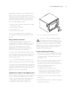
ANTENNA
FFA
FILAMENT AND
HIGH VOLTAGE
TERMINALS
FIGURE 24: High Voltage Diode
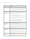
FIGURE 25: Magnetron