ADJUSTING THE OVEN DOOR
WARNING: Procedure should be done while
oven is hot. As a result, exercise extreme
caution when adjusting the door.
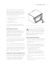
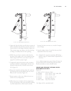
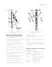
1. Open the oven door and remove the plastic caps.
2. Ensure that the 3 screws on each side of the door
are tight.
3. Remove the control panel, two
11
/
32
” nuts and
wiring from I/O board.
4. Loosen the hex screws and close the door.
5. Tap the center of the door to allow door and
frame to align properly.
6. Tighten screws and reinstall the control panel.
7. Plug in the oven and perform a MW leak test (see
page 31 for instructions).
Critical Adjustment Notes
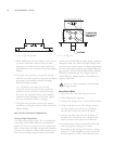
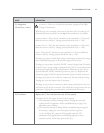
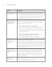
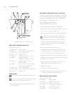
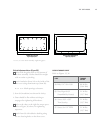
1. The doors in Figures 27 and 28 are adjusted
incorrectly. Note how the bottom (Figure 27)
and top (Figure 28) of the door can be rotated
away from the Flange.
CORRECTIVE ACTION: Loosen the hex screws
and push the door towards the flange and re-
tighten. The hinge springs will naturally pull the
door to the flange. Tapping the center ensures a
level surface and a proper seal, as opposed to
pushing one end (which could cause the opposite
end to lift away from the flange).
Pull the door open only 0.25” (6 mm) and let go
of the handle. The door must completely snap shut
on its own. If the door sticks and force is needed
to finish closing it, it is out of adjustment.
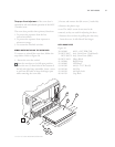
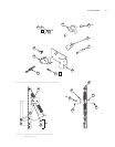
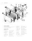
NOTE: See Figure 26, page 37, Items 43-46 for illus-
tration of hardware.
WARNING: Check for excessive Microwave
Leakage after adjusting the Cook Door. See
page 31 for proper procedure.
PREPARING THE OVEN FOR SWITCH ADJUSTMENT
1. Disconnect the power to the oven and remove
left and right side covers.
2. Ensure oven door assembly is properly adjusted
and all mounting screws are secured (see previous
section on adjusting the oven door).
3. Ensure the left and right hinge assemblies are
properly mounted to the oven flange.
Oven Burn-In Procedure
If the oven is already at its set temperature at the
time of service, skip this procedure.
1. Apply power to oven.
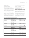
2. Simultaneously press the
BACK and ENTER
keys.
3. Enter 8-6-4-8 (
U-N-I-T), then press ENTER.
4. Press
BURN-IN. The oven will warm up and
idle for 25 minutes.
ADJUSTING THE PRIMARY AND SECONDARY
INTERLOCK SWITCHES - OLD SWITCH SETUP
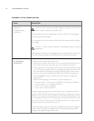
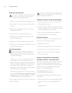
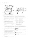
The old switch assembly is identifiable by the pri-
mary and secondary interlock switches being
located on the left side of the oven. Also, the serial
number of the oven will follow the formatting
below (X = variable digit/letter):
NGC-XXXXX (North America)
NGCXX-XXXXX (International)
To properly adjust the switches, follow the proce-
dure below:
1. Ensure the oven door is adjusted properly. Refer
to the previous section on adjusting the oven
door.
2. Unplug the oven.
THE OVEN DOOR
38


