


97-0019-01-01 11
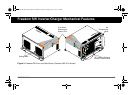
Freedom SW Inverter/Charger Mechanical Features
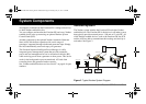
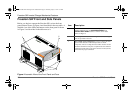
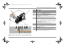
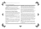
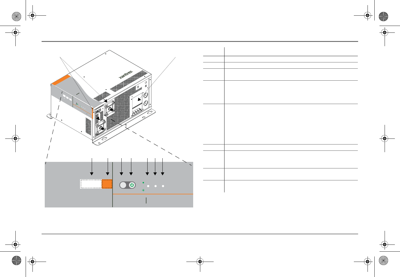
Figure 5
Isometric View of the Front Panel and AC/DC Side Panel
XANBUS INTERFACE STACKING
FREEDOM SW INVERTER/CHARGER
CLEAR FAULT
RESET
INVERTER
ENABLE
INVERTER
ENABLED
AC IN FAULT
GEN
SUPPORT
CHARGING WARNING
FREEDOM
SW
3012
FREEDOM SW
3012
CLEAR FAULT
RESET
INVERTER
ENABLE
INVERTER
ENABLED
AC IN
FAULT
GEN
SUPPORT
CHARGINGWARNING
3
1
4
2
56
79 8
Item Description
1 DC terminals.
2 AC wiring compartment access panel with compartment cover on.
3 FAULT LED turns on solid if a fault condition occurs and flashes
intermittently when a WARNING condition is active.
4 When AC is present and qualified, the AC IN LED will turn on solid
indicating also that AC is passing through.
CHARGING LED flashes intermittently when the Freedom SW is in
charge mode and is producing DC output to charge your batteries.
5 INVERTER ENABLED indicates the invert mode is enabled. This is
different from the inverter being “on”. When enabled the inverter can
be on or off. When disabled, the inverter is always off. If AC is present
and invert mode is enabled, this LED remains illuminated even though
AC power is being passed through.
GEN SUPPORT LED flashes intermittently when the inverter is in
generator support mode and is assisting the generator.
6 INVERTER ENABLE button is used to enable or disable the inverter.
7 CLEAR FAULT RESET button is used to clear any active faults if
pressed momentarily. If held down for more than three seconds, the
unit will reset (reboot) itself.
8 STACKING port is used to connect two inverter/chargers together for
stacked operation. This is required only for stacking in series.
9 XANBUS INTERFACE ports are used to connect Xanbus-enabled
devices including the optional SCP and AGS.
Freedom SW 3K2K InvChg Owners Guide.book Page 11 Thursday, July 31, 2014 1:42 PM