


Chapter 2 25
Front and Rear Panel Features
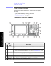
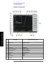
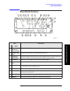
Front Panel Overview
Front and Rear Panel Features
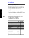
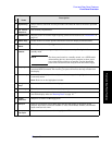
7 System Keys Access features used with all analyzer modes and affect the state of the entire spectrum
analyzer.
8 Vol. Control/
Earphones
Not currently implemented.
9
PROBE PWR Supplies power for external high frequency probes and accessories (see “Accessories” on
page 71).
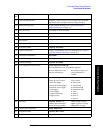
10
Marker Keys Enable markers to obtain specific information about the displayed measurement.
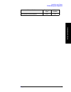
11
EXT TRIGGER
INPUT
Enables you to externally trigger measurements.
12
POWER
ON/OFF
Turns the analyzer on. A green light indicates power on. A yellow light indicates
standby mode.
NOTE The front-panel switch is a standby switch, not a LINE switch
(disconnecting device); the analyzer continues to draw power
even when the line switch is in standby. Use the detachable
power cord to disconnect the analyzer from the mains supply.
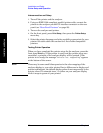
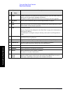
13
Help Key Press the Help key, then any other key to get a short description of that key and the
associated SCPI command. The next key you press will remove the help window from
the display.
14
Window Keys Next Window: On displays with multiple windows, changes the highlighted window that
is currently active.
Zoom: Zooms in on the highlighted window.
15
Navigation
Keys
Move cursor between fields on the display.
16
Return Key Exits the current menu and returns to the previous menu.
17
Data Controls Change the numeric value of an active function. Entries appear in the active function
area of the display. Also see “Entering Data” on page 37.
18
Floppy
Disk Drive
Accepts a 3.5 inch 1.44 MB floppy disk.
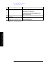
19
RF Input Input for an external signal. Make sure that the total power of all signals at the
analyzer input does not exceed +30 dBm (1 watt). The E4446A, E4447A, and E4448A
input connector is 2.4 mm.
20 IF Input, 1st
LO Output
Allows connections for external mixing (Option AYZ)
Item
Description
# Name