


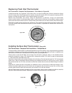
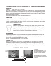

Replacing The Digital Thermometer
Turn off breaker before disconnecting wires.
If the thermometer does not register correctly you will need to check the following:
1. Check the voltage on the load side of the transformer. It should be 12 volts.
2. If the voltage is not 12 volts on the load side of the transformer, check the
line side to confirm that proper voltage is reaching the transformer.
3. If you have 115 volts on the line side and nothing on the load side you will
need to change the transformer.
4. If the transformer checks good you will need to change the digital display.
This is done by removing the two screws from the front of the display and
pulling out the whole module. Take the two wire nuts off the incoming
power located behind the display. Pull the probe out through the insulated
section. Push the new probe through the same hole in the insulated
section and secure. Hook the two wires back to the incoming power from
the transformer. Replace the display on the door section and secure with
the screws. Turn the power on and check the display.
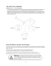
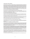
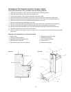
Description Of Numbered Parts, Figure #24 and #25
1. Junction Box
2. Optional wire guard for vapor proof light
3. Plastic coated glass globe for vapor proof light
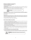
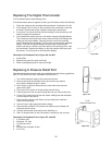
Replacing A Pressure Relief Port
After determining the pressure relief port is defective use the following guidelines:
(NOTE: THE HEATER IS NOT AVAILABLE SEPARATELY.)
1. Turn off the electrical supply to the pressure relief port.
2. Remove the inside and outside louvers and remove any sealant
that might be holding the port in place.
3. Open square J. Box and disconnect two small white wires and one
green wire to PRP.
4. Pull out the PVC portion of the port along with the wiring.
5. Feed the wire from the new port through the hole up to the junction box.
6. Put the PVC portion back into the wall section making sure that the heater
is in the interior of the walk-in.
7. Seal around the interior with silicone (not provided) then install the
interior louvered flange.
8. Push the vent in tight against the interior flange.
9. Seal around the exterior PVC portion with silicone (not provided) and
install the exterior louver.
10. Connect the electrical wires and turn the electricity on.
11. After 15 minutes check to see if the heater is working on the new port.
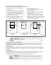
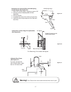
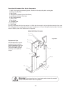
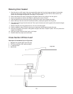
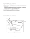
Description Of Numbered Parts, Figure #27, and #28
1. 4" Urethane wall
2. 45 degree 1/2" hole
3. 1/2" groove to hole
4. Wire
5. Junction Box at header of door
6. 2 1/2" hole
22
Figure #25
2 1/2"
Pressure Relief Port
Figure #27
Figure #28