


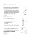

Input Voltage
12 VAC Only DO NOT CONNECT THIS UNIT TO 120VAC
The line voltage of 120VAC shall be connected to the two (2) black leads, one with a white sleeve, from the transformer provided and
attached to the exterior of the junction box located on the interior of the cooler above the door. These wires will be found within the
junction box. Connect one black to the hot leg & one black with white sleeve to the neutral leg. Connect the green wire to ground. The
two yellow wires with the fork terminals protruding from the center of the junction box must be connected to the 12VAC side of the
transformer. Additional length may be obtained by loosening the black bushing and withdrawing ample wire to make the connection.
Reference the wiring diagram on this sheet.
NOTE: (Prior to December 2002 both 120Vleads were black & 12V black & white)
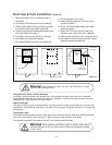
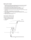
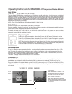
Back Up Power
Remove the faceplate of the unit and install a 9 Volt battery to the harness.
During a power failure, the unit will remain dark. The battery backup will allow a momentary check of temperature and will produce an
audible alarm should the storage temperature exceed the alarm set points.
To check the temperature when in battery backup mode, depress the reset button. The current temperature will appear. The alarm,
if activated, will silence for 5 minutes. After that, the unit will then become active again. This procedure will continue until the
temperature returns within the designated set points.
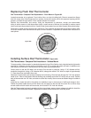
Programming Unit
To set the High Set Point temperature, depress the Set button until HSP appears. Push again to display
the factory setting. Using the adjust buttons set the desired upper limit temperature.
To set the Low Set Point temperature, depress the Set button until LSP appears. Push again to display the
factory setting. Using the adjust buttons set the desired lower limit temperature.
NOTE: If the programming sequence is interrupted for more than 15 seconds, or not completed to the point
where the display flases once, the unit will automatically revert back to the temperature display mode and
to the factory settings for HSP & LSP without acknowledging any new set values.
Normal Operation
Following successful programming, if at any time the temperature within the cooler or freezer travels beyond the set limits (HSP
or LSP), the display will flash and the alarm will sound. To silence the alarm push the reset button. The alarm will stop for 5 min-
utes. The display will continue to flash indicating an alarm condition and will continue to do so until the temperature within the
unit returns within programmed settings. If after 5 minutes the temperature remains outside of desired conditions, the alarm will
then sound again. The process for silencing the alarm may be repeated.
Three dots…on display indicates that the battery is low or is not installed.
Calibration "CAL"
Calibration "CAL": This temperature display on this unit may be calibrated either up or down if required. This is preset by the
manufacturer. Do not attempt to change without checking with the customer service department at W.A. Brown & Son, Inc.
Call 1.800.640.0593 for assistance.
During new installation it is suggested that the High Set Point (HSP) be temporarily set at 100˚ F and the Low Set Point (LSP) to
–30˚ F to eliminate any unnecessary alarms when power is activated to this unit and the refrigeration in the cooler or freezer has yet
to be started.
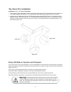
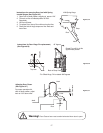
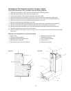
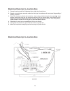
120 VOLT SERVICE
CONNECT INCOMING 120 VOLT SERVICE TO THE 2
BLACK WIRES AND GREEN GROUND WIRE FROM
TRANSFORMER. THESE WIRES ARE IN THE JUNCTION
BOX ON INSIDE OF DOOR PANEL. SEE FIGURE 1.
CONTROL VOLTAGE FOR TAI 2000D-12
CONNECT WHITE AND BLACK WIRES WITH SPADE
TERMINAL CRIMPED ON ENDS LOCATED IN JUNCTION
BOX TO SECONDARY TERMINALS ON TRANSFORMER.
SEE FIGURE 1 & 2.
Figure 1
Figure 2
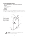
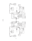
TAI 2000D-12 WIRING DIAGRAM
120 VOLT
SERVICE
FROM TRANSFORMER 2 BLACK & GREEN
BACKSIDE OF TAI PANEL
Black wire with spade terminal 10vac
White wire with spade terminal 10vac
THESE WIRES IN JUNCTION BOX
Operating Instructions for TAI-2000D-12 Temperature Display & Alarm
26