


3
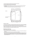
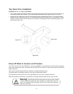
Floorless Walk-In Layout
Floor Spline Layout and Installation
Warning! When W. A. Brown does not provide the insulated floor, check
carefully before installing the walk-in for appropriate thermal breaks. Severe
floor heaving problems occur when floors are not adequately insulated. Consult
the W. A. Brown Working Data Catalog for details.
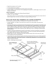
1. Mark on the building floor the exact area the walk-in will occupy.
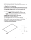
2. Lay the spline out as indicated on the spline layout drawing (See Figure #2) which is furnished with each walk-
in. Each section is numbered and must be layed out as shown in order for the wall panels to lock down
properly. Measure diagonally from corner to corner to be sure the floor spline is square.
3. The entire floor spline must be leveled from the highest point.
Warning! On walk-ins larger than 10' x 10' it is recommended that a
transit level be used to level the floor spline rather than a spirit level.
4. Determine where shims are needed for leveling, and cut them to the width of the spline. (W. A. Brown does
not furnish these shims.)
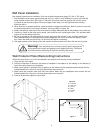
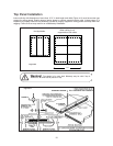
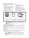
5. Fasten the spline to the floor using ramset studs, screws,
expansion bolts, etc. (See Figure #3)
6. Seal all open areas between the spline and floor
using grout or a siliconesealant.
(Not provided by WAB.)
7. Seal all joints between sections of
spline, similarly to above.
8. Locate and install metal
NSF cove molding after
walls are installed.
Figure #2
Figure #3
Ramset
Studs
or Screws
NSF Cove Molding
is either 5 1/2" high
or 2 1/2" high
Floor spline is either 4 1/4"
high or 1 5/8" high
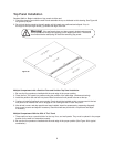
Cam Lock Installation
All panels are connected with a mechanical Cam lock which is activated by using a hex
wrench (included with your shipment). There are both a male section, and a female
section. The locks are foamed in place and securely anchored to provide a solid
connection, when the locking arm is tightened around the locking pin which is located in
the female section.
To operate the latch, insert the wrench through the access hole which is located on the
inside of each panel. Turn the wrench counter-clockwise to fully unlock and retrieve the
locking arm. Pushing together the two panels you wish joined, you will then turn the
wrench one quarter turn clockwise. Continue to turn the wrench until you feel the panels
lock together. You should feel the lock hit the stop position.
Some custom panels may have specialized lock locations. They will be so marked. Follow those markings when
connecting these panels.
Make sure you have the panels in the correct and final position before locking, as continued locking and unlock-
ing may result in less than satisfactory operation.