


24
SERVICE (cont.)
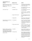
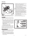
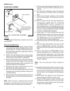
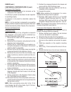
AUGER SHAFT ASSEMBLY
Auger Shaft Assy
Auger Shaft Bushing
Cooling Drum Seal
Auger Shaft Seal
Hopper Drum Seal
FIG. 5 AUGER SHAFT ASSEMBLY
Location:
The Auger Shaft Assembly is located in each of the
cooling drums.
Removal and Replacement:
1. Drain, remove and clean hopper; refer to the Rec-
ommended Daily Weekly Cleaning Section of this
manual, page 12, for proper cleaning procedures.
Discard the auger shaft seal, hopper/drum seal and
faucet spool o-rings.
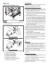
2. Remove the #8 locking screws securing auger
motor cover to the cooling drum mount assembly;
remove cover and set aside for reassembly.
3. Remove the #8 locking screw on the lower right side
(viewed from front) of the auger motor mounting
bracket securing the auger motor run capacitor. Set
capacitor aside with wires attached.
4. Disconnect the auger motor terminal from the
terminal on the main wiring harness.
5. Remove the remaining #8 locking screws securing
the auger motor mounting bracket to cooling drum
mounting bracket.
6. Remove motor with mounting bracket, drip tray (if
present) split pin and torsion spring bearing as an
assembly.
NOTE - When removing or installing motor and shaft
assemblies, be sure the split pins are turned to a posi-
tion that will clear the torque sensor circuit board.
7. Pull the auger shaft assembly straight out of cool-
ing drum. Inspect the shaft for abnormal wear or
scoring.
8. From the front of dispenser, remove the seal and
blue bushing from cooling drum and discard
them.
9. Clean seal and busing surfaces of the cooling
drum very thoroughly. All old lubricant must be
removed.
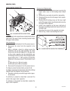
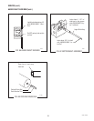
10. Refer to Fig 6A and slip new blue bushing into
cooling drum. Lightly lube I.D. of bushing
with #M2550.0000 “Lubri-lm” providedin Kit
#28106.0000 (CDS-2) or #28106.0001 (CDS-3). Do
not use anything such as a cotton swab that might
leave lint or unravel. DON NOT GET ANY LUBE ON
THE SEAL COUNTERBORE SURFACE.
11. Lightly lube I.D. of new cooling drum seal with
#M2550.0000, provided in kit. Use care not to get
any lube on O.D. of seal. Place seal on insertion
tool #28395.0000, as shown in Fig. 6B. Make sure
open face of seal is toward cooling drum.
12. Push seal into bore until it is firmly seated; remove
tool.
13. Clean the auger shaft assembly, then wipe a small
amount of #M2550.0000 “Lubri-film” (provided in
kit) over the first two inches of the front end of the
shaft.
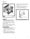
14.Placea small amountof#29563.0000 “Krytox”
lubricant (provided in kit in a plastic cap) on the
end of the motor shaft (about 1 1/2”) and a thin
film in the groove. Install auger shaft assembly onto
the motor shaft. See Fig. 6C. Do not use too much
“Krytox”lubricant.
NOTE - This is the onlyplace “Krytox” lubricantis
used.
15. Assemble motor/shaft assembly as shown in Fig.
6C, then install assembly into cooling drum. Make
sure the pins do not hit the sensor board and cool-
ing drum seal is not dislodged as the shaft passes
through.
16. Secure motor and capacitor to the cooling drum
mounting bracket. Install rear motor cover.
17. Refer to Initial Setup for hopper assembly and
installation procedures. Be sure to use new hop-
per/drum seal, auger shaft seal and faucet spool
o-rings when reassembling.
P1758
27646 122200