


32
SERVICE (cont.)
COMPRESSOR & COMPONENTS (CDS-3) (cont.)
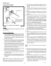
Compressor Run Capacitor:
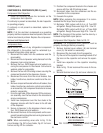
1. Check for continuity across the terminals on the
compressor run capacitor.
If continuity is present as described, the run capacitor
is operating properly.
If continuity is not present as described, replace the
capacitor.
NOTE: If all the electrical components are operat-
ing properly and the compressor does not operate,
there is an internal mechanical problem. Replace the
compressor.
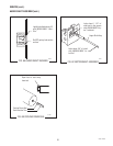
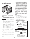
Removal and Replacement:
Compressor Assy:
NOTE: Before removal of any refrigeration component
the refrigerant in the system must be reclaimed by a
licensed refrigeration repair person.
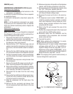
1. Disconnect the tubes from the condenser, accu-
mulator also remove access valve and tube..
2. Disconnect the compressor wiring harness from
the dispenser main wiring harness.
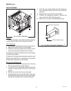
3. Remove the four .312”-18 screws, keps nuts and
washers securing the compressor to the chassis.
Set screws, nuts and washers aside for reassem-
bly.
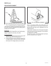
4. Remove the four #8-32 locking screws securing
the component bracket to the dispenser chassis.
5. Pull the component bracket, with wires attached,
out of the chassis far enough to gain access to the
compressor.
6. Disconnect the compressor wiring harness from
the compressor.
7. Remove the two #8-32 screws securing the con-
tactor mounting bracket to the dispenser base.
8. Remove the contactor mounting bracket, contactor,
contactor cover and the compressor wiring harness
as an assembly. Set aside for reassembly.
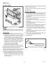
9. Disconnect the fan leads from the main wiring
harness.
10. Remove the three #6 thread cutting screws secur-
ing the fan to the condenser shroud. Remove the
fan and set aside for reassembly.
11. Slide the compressor out the right side of the
dispenser.
12. Remove the four grommets and sleeves from
the old compressor and install them on the new
compressor.
13. Slide new compressor into position on the dispenser
chassis, with the tube connections to the front.
14. Secure compressor to the dispenser chassis using
four .312”-18 screws, washers and nuts.
15. Install the fan on the condenser shroud and secure
with three #6 thread cutting screws.
16. Reconnect the leads on the fan to the main har-
ness.
17. On dispensers serial number CDS0019500 - up
install the contactor bracket, contactor, contactor
cover and compressor wiring harness as an as-
sembly. Secure contactor bracket to the chassis
using two #8-32 screws.
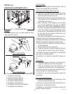
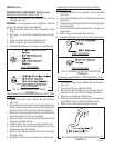
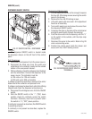
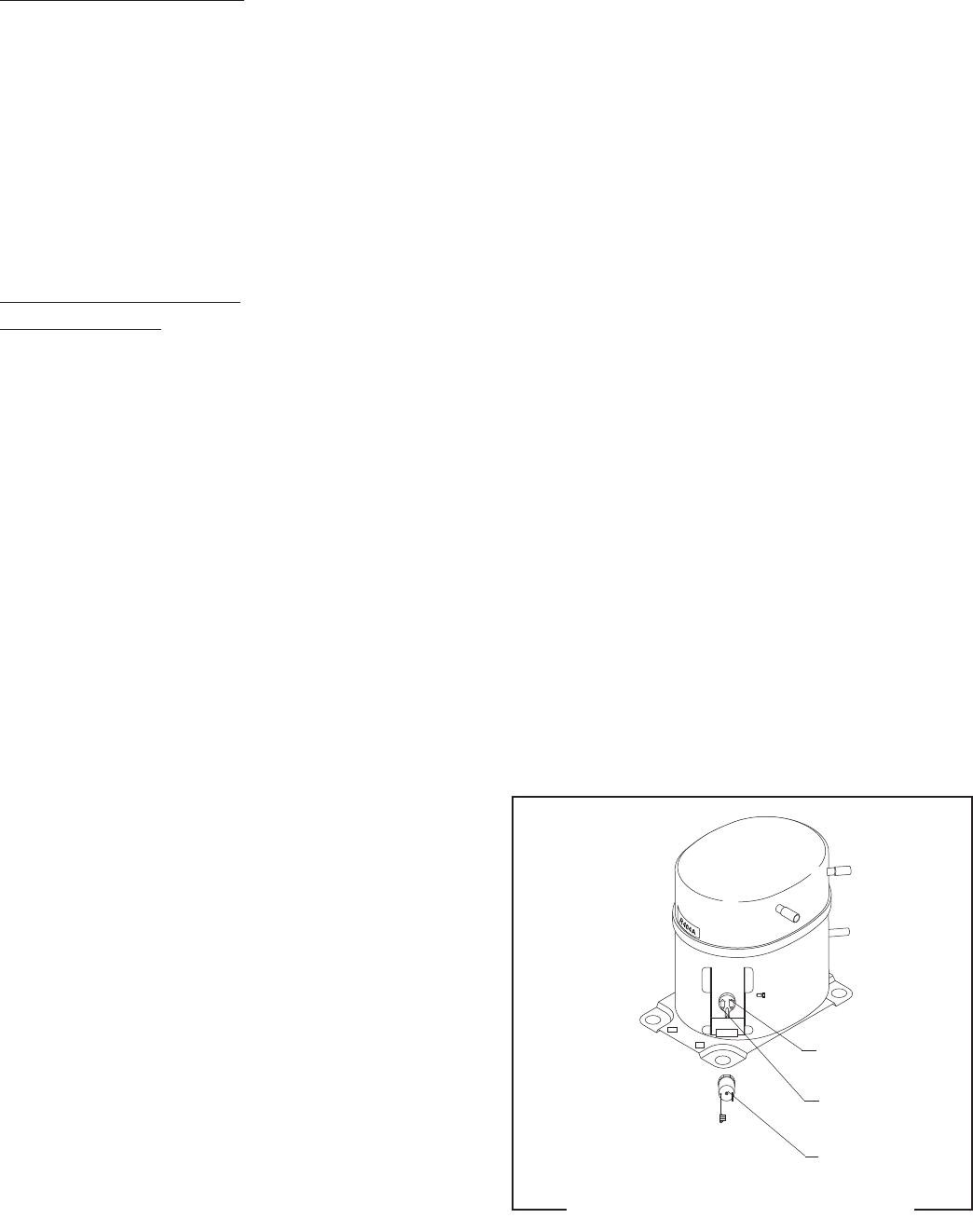
18. Refer to Fig.17A and reconnect the wires to the
compressor.
19. Position the component bracket in the chassis and
secure with four #8-32 locking screws.
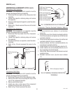
20. Reconnect tubes from the condenser and the
accumulator to the compressor, also reconnect
access valve and tube.
21. Evacuate the system.
NOTE: When replacing the compressor it is recom-
mended that the dryer also be replaced.
22. Dispensers prior to serial number CDS0019500
recharge system with 25 oz. of Type R404A re-
frigerant. Design Pressures: High 320 - Low 44
Dispensers serial number CDS0019500 - up re-
charge system with 22 oz of type R404A refrigerant.
Design Pressures: High 380 - Low 52
NOTE: The charging of the system must be done by a
licensed refrigeration repair person.
RED from
Relay T2
WHI from
Relay T4
BLKfrom
Relay T-5
FIG. 17A COMPRESSOR TERMINALS
P1819
27646 122200