


34
SERVICE (cont.)
CONTACTOR - ELECTRONIC CONTROL
6. Disconnect the black wires from contactor termi-
nals #6 & #8 (#5 & #6, CDS-3 first type contac-
tor).
7. With ON/OFF switch in the “ON” position, connect
the dispenser to the power source and check for
continuity across terminals on contactor.
If continuity is not present as described, on CDS-3 first
type contactors, replace contactor. If continuity is not
present between terminals #6 & #8 as described on all
CDS-2 contactors and CDS-3 second type contactors,
check for continuity across terminals #2 and #4.
If continuity is present as described, disconnect the
dispenser from power source and reconnect black
wires to terminals #2 and #4, the contactor will oper-
ate properly.
If continuity is not present as described, replace the
contactor.
Removal and Replacement:
1. Disconnect the wires from the contactor.
2. Remove the two #8-32 locking screws securing
the contactor to the component bracket. Remove
and discard contactor.
3. Install the new contactor on the component bracket
using two #8-32 locking screws.
4. Refer to Fig. 22 and reconnect the wires.
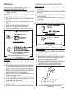
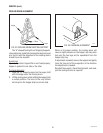
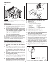
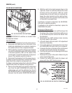
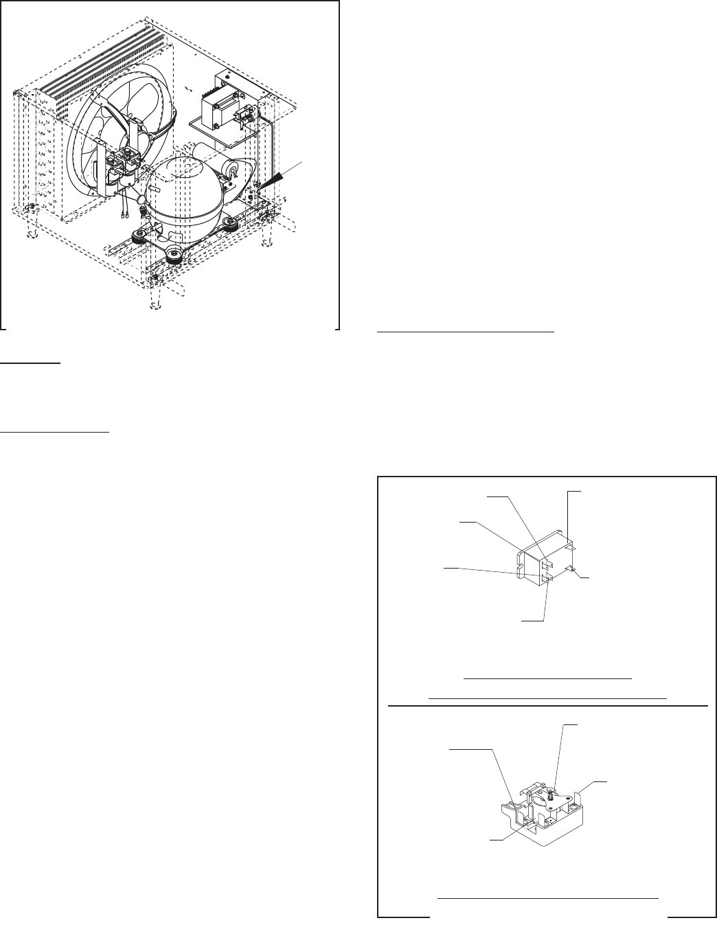
FIG. 22 CONTACTOR TERMINALS
P1333
R22
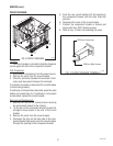
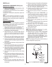
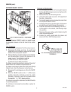
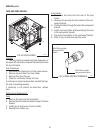
FIG. 21 CONTACTOR - ELECTRONIC CONTROL
Location:
The contactor is located inside the dispenser chas-
sis on the lower outside of the component bracket.
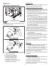
Test Procedures:
1. Disconnect the dispenser from the power
source.
2. Disconnect white/black wire from contactor termi-
nal #0 (terminal #2, on CDS-3 first type contactor)
and brown/black from terminal #1.
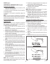
3. With a voltmeter, check the voltage across the
white/black wire and the brown/black wire and
the ON/OFF switch in the “ON” position. Connect
the dispenser to the power source. The indication
must be:
a) 120 volts ac for 120 volt models.
b) 230 volts ac for 230 volt models.
4. Disconnect the dispenser from the power
source.
If voltage is present as described, proceed to #5.
If voltage is not present as described, refer to the
Wiring Diagram and check the dispenser wiring har-
ness.
5. Check for continuity across contactor terminals
#0 & #1 (#1 & #2, CDS-3 first type contactor).
If continuity is present as described reconnect the
white/black wire and the brown/black wire to the
contactor and proceed to #6.
If continuity is not present as described, replace the
contactor.
P1342
ALL CDS-2 CONTACTORS
CDS-3 SECOND TYPE CONTACTORS
CDS-3 FIRST TYPE CONTACTORS
27646 122200
Terminal #0
WHI/BLKfromMainHarness/
Power Cord/Compressor
Terminal #1
BRN/BLK from Main
Harness/Control Board
Terminal #6
BLKfromMain
Harness/Power Cord
Terminal #8
BLKfromCompressor
Harness
Terminal #2
Terminal #4
Terminal #1
BRN/BLK from Main
Harness/Control Board
Terminal #6
BLKfromMain
Harness/Power Cord
Terminal #2
WHI/BLKfromMainHarness/
Power Cord/Compressor
Terminal #5
BLKfromCompressor
Harness