


41
SERVICE (cont.)
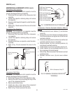
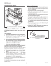
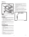
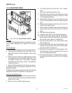
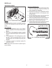
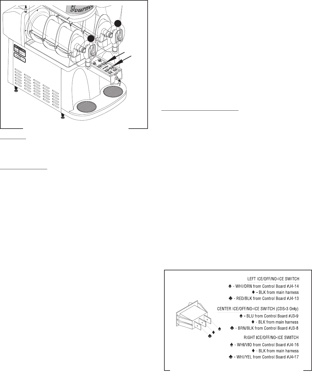
ICE/OFF/NO ICE SWITCHES
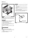
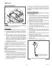
FIG. 36 ICE/OFF/NO ICE SWITCH TERMINALS
P1334
FIG. 35 ICE/OFF/NO ICE SWITCHES
P1343
Location:
The ICE/OFF/NO-ICE switches are located inside
the dispenser drawer.
Test Procedures:
1. Disconnect the dispenser from the power source.
2. Disconnect the black wire from the switch to be
tested and white/black from contactor located on
the outside bottom of the component bracket .
3. With a voltmeter, check the voltage across the black
wire and the white/black wire and all other switches
in the down position (“ON”) to the center of the
control panel. Connect the dispenser to the power
source. The indication must be 5 volts dc.
4. Disconnect the dispenser from the power source.
If voltage is present as described, reconnect the white/
black wire to the contactor and proceed to #5.
If voltage is not present as described, refer to the Wiring
Diagram and check the dispenser wiring harness.
5. Remove the white/yellow wire and the white/violet
wire from the right ICE/OFF/NO-ICE switch, the
white/orange wire and the red/black from the left
ICE/OFF/NO-ICE switch, or the brown/black wire and
blue wire from the center ICE/OFF/NO-ICE switch.
6. With the switch to be tested pressed down on the
right side, check for continuity between the center
terminal and the left terminal. With the switch
pressed down to the left, check for continuity be-
tween the center terminal and the right terminal.
Continuity must not be present when neither side
of the switch is pressed down.
If continuity is present as described, the ICE/OFF/NO-
ICE switch is operating properly.
If continuity is not present as described, replace the
ICE/OFF/NO-ICE switch.
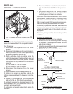
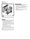
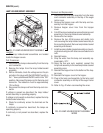
Removal and Replacement:
1. Pull the dispenser drawer out until the drawer hits
the drawer stop. Using a screwdriver gently pry up
on the drawer stop and remove the drawer from
the dispenser.
2. Remove the four #8-32 locking screws securing
the switch panel to the drawer.
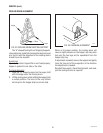
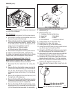
3. Lift switch panel with wires and L.E.D./adjustment
board as an assembly.
4. Turn switch panel over and remove the wires from
the ICE/OFF/NO-ICE switch that is to be replaced.
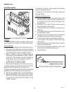
5. Compress the clips on the back of the control panel
and gently push switch through the opening.
6. Push the new switch into the opening until the clips
snap into position.
7. Reconnect the wires to the switch. Refer to Fig. 36
when reconnecting wires.
8. Position the switch panel inside the drawer and
secure with four #8-32 locking screws.
27646 122200