


28
R22
R22
R22
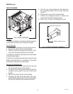
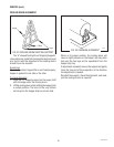
120V COMPRESSORS
SERVICE (cont.)
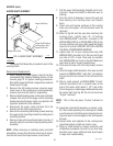
COMPRESSOR & COMPONENTS (CDS-2)
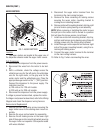
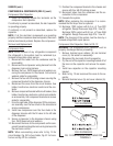
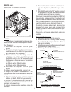
FIG. 11 COMPRESSOR ASSY
3 2 5 6
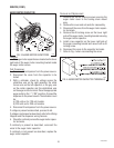
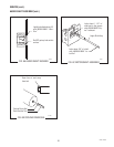
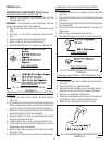
FIG. 12 COMPRESSOR ELECTRICAL COMPONENTS
P1344
Test Procedures:
WARNING: The compressor start capacitor must be
properly discharged before proceeding.
Compressor Start Relay: Refer to FIG. 12
1. Disconnect the dispenser from the power source.
2. Remove compressor terminal cover retainer (6)
and compressor terminal cover (5).
3. Disconnect the black wire from the thermal over-
load protector (3) and white/black wire from the
compressor start relay (1).
4. With a voltmeter, check voltage across the black
wire and the white/black wire and the ON/OFF
switch in the “ON” position, DAY/NIGHT switch in
the “DAY” position and the ICE/OFF/NO ICE switch
in the “ICE” position. Connect the dispenser to the
power source. The indication must be 120 volts ac
for two wire 120 volt models or 230 volts ac for
two wire 230 volt models.
5. Disconnect the dispenser from the power source.
If voltage is present as described, proceed to #6.
If voltage is not present as described, refer to the Wiring
Diagram and check the dispenser wiring harness.
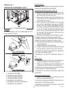
6. Disconnect the two black wires from the compres-
sor start capacitor.
7. Remove relay from the compressor.
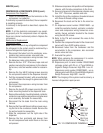
8. Check for continuity across the upper left terminal
and the right pin socket on the rear of the relay.
If continuity is present as described, the compressor
start relay is operating properly.
If continuity is not present as described, replace re-
lay.
Compressor:
1. With the compressor start relay (1) removed, dis-
connect the black wire from the compressor.
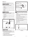
2. Check for continuity across the terminal on the
compressor and the left pin on the compressor.
If continuity is present as described, the electrical part
of the compressor is operating properly.
If continuity is not present as described, replace the
compressor.
Thermal Overload Protector:
1. Check for continuity across the terminals on the
thermal overload protector (3).
If continuity is present as described, the thermal over-
load protector is operating properly.
If continuity is not present as described, replace the
thermal overload protector.
Location:
The compressor assy is located inside the front
of the dispenser chassis.
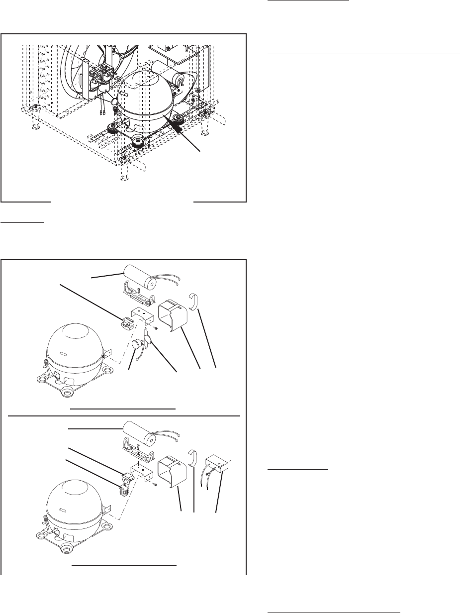
1. Compressor Start Relay
2. Overload Protector Retainer
3. Thermal Overload Protector
4. Compressor Start Capacitor
5. Compressor Terminal Cover
6. Compressor Terminal Cover Retainer
7. Compressor Run Capacitor
P1342
1 4
4
3
1
5 6 7
230V COMPRESSORS
27646 122200