


30
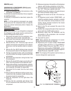
Compressor Thermal Overload Protector (230V):
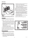
Refer to FIG. 12
1. Remove terminal cover retainer (6) and terminal
cover (5).
2. Disconnect the black wire from the thermal overload
protector.
3. Pull thermal overload protector off of the compressor
pin and discard.
4. Push new thermal overload protector onto the com-
pressor pin.
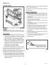
5. Refer to Fig. 15 and reconnect the wire.
6. Reinstall terminal cover (5) and cover retainer (6).
SERVICE (cont.)
COMPRESSOR & COMPONENTS (CDS-2) (cont.)
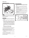
Compressor Thermal Overload Protector (120V): Refer
to FIG. 12
1. Remove terminal cover retainer (6) and terminal
cover (5).
2. Disconnect the wire from thermal overload protector
to the compressor and the wire from the compressor
wiring harness to the thermal overload protector.
3. Remove overload protector retainer (2) and thermal
overload protector (3) as an assembly.
4. Remove retainer (2) from overload protector (3) and
discard overload protector.
5. Install retainer (2) on new overload protector (3).
6. Install retainer (2) and overload protector (3) on the
compressor terminal bracket.
7. Refer to Fig. 15 and reconnect the thermal overload
protector wires.
8. Reinstall terminal cover (5) and cover retainer (6).
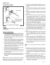
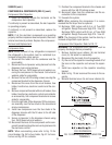
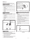
FIG. 15 THERMAL OVERLOAD PROTECTOR
TERMINALS
P1339
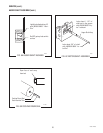
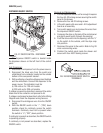
FIG. 14 COMPRESSOR START RELAY
TERMINALS
P1338
120V DISPENSERS
230V DISPENSERS
120V DISPENSERS
230V DISPENSERS
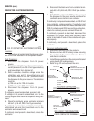
Compressor Start Relay: Refer to FIG. 12
1. Remove the terminal cover retainer (6) and the
terminal cover (5)
WARNING: The compressor start capacitor must be
properly discharged before proceeding.
2. Disconnect the wires from the compressor start
relay.
3. Pull relay (1) off of the compressor pins and dis-
card.
4. Push new relay onto the compressor pins.
5. Refer to Fig. 14 and reconnect the wires.
6. Reinstall terminal cover (5) and cover retainer (6).
Compressor Run Capacitor (230V Dispensers Only):
Refer to FIG. 12
1. Remove terminal cover retainer (6) and terminal
cover (5).
2. Disconnect the run capacitor leads.
3. Remove the #6 crimptite screw securing the run
capacitor to the rear of the component bracket.
4. Remove run capacitor and discard.
5. Place new run capacitor on the rear of component
bracket and secure with #6 crimptite screw.
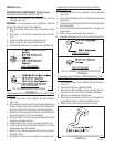
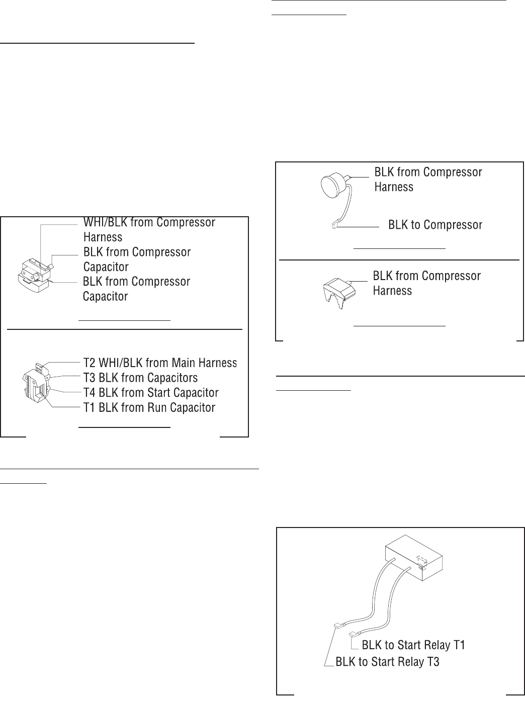
6. Refer to Fig. 15A and reconnect the wires.
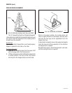
FIG. 15A COMPRESSOR RUN CAPACITOR
TERMINALS
P1816
27646 122200