


29
SERVICE (cont.)
COMPRESSOR & COMPONENTS (CDS-2) (cont.)
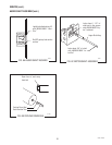
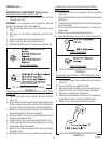
Compressor Start Capacitor:
1. Check for continuity across the terminals on the
compressor start capacitor.
If continuity is present as described, the start capacitor
is operating properly.
If continuity is not present as described, replace the
capacitor.
NOTE: If all the electrical components are operating
properly and the compressor does not operate, there is an
internal mechanical problem. Replace the compressor.
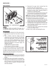
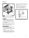
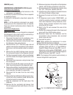
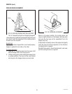
Removal and Replacement:
Compressor Assy:
NOTE: Before removal of any refrigeration component
the refrigerant in the system must be reclaimed by a
licensed refrigeration repair person.
1. Disconnect the tubes from the condenser and the
accumulator.
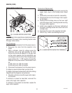
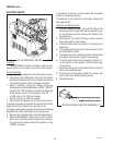
2. Disconnect the compressor wiring harness from the
dispenser main wiring harness.
3. Remove the four .25-20 keps nuts and washers se-
curing the compressor to the chassis. Set nuts and
washers aside for reassembly.
4. Remove the four #8-32 locking screws securing the
component bracket to the dispenser chassis.
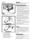
5. Disconnect the wires from the circuit breaker, fuse
holder, transformer, electronic control and the con-
tactor.
6. Remove component bracket with circuit breaker, fuse
holder, transformer, electronic control and contactor
as an assembly. Set component bracket and screws
aside for reassembly.
7. From the right side of the dispenser lift the compres-
sor assembly over the four studs in the chassis and
remove compressor.
8. Install new compressor over the four studs in the
dispenser chassis with the fill valve to the left side
of the dispenser.
9. Secure compressor to the dispenser chassis using
four .25-20 keps nuts and washers.
10. Reconnect the wires to the components on the com-
ponent bracket and plug the main wiring harness into
the electronic control.
NOTE: When reconnecting wires refer to Fig. 10 for
circuit breaker, Fig. 34 for fuse holder, Fig. 51 for trans-
former and Fig. 22 for contactor.
11. Position the component bracket in the chassis and
secure with four #8-32 locking screws.
12. Reconnect tubes from the condenser and the ac-
cumulator to the compressor.
13. Evacuate the system.
NOTE: When replacing the compressor it is recom-
mended that the dryer also be replaced.
14. Recharge 120V system with 8.4 oz. of Type R22
refrigerant. Design Pressures: High 210 - Low 32
Recharge 230V system with 9.5 oz. of Type 404A
refrigerant. Design Pressures: High 215 - Low 40
NOTE: The charging of the system must be done by a
licensed refrigeration repair person.
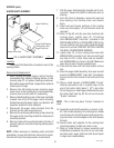
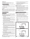
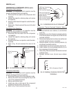
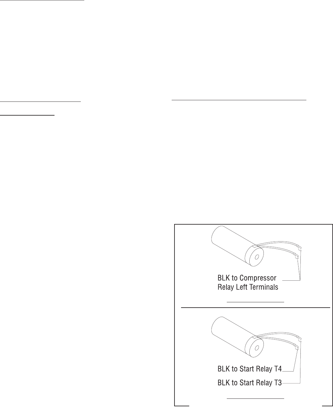
Compressor Start Capacitor: Refer to FIG. 12
WARNING: The compressor start capacitor must be
properly discharged before proceeding.
1. Remove terminal cover retainer (6) and terminal
cover (5). Set aside for reassembly.
2. Disconnect the two leads from the capacitor.
3. Pry the end of the capacitor mounting bracket off of
the boss on the capacitor and remove the capaci-
tor.
4. Install new capacitor on the capacitor mounting
bracket.
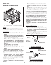
5. Refer to Fig. 13 and reconnect the wires to the ca-
pacitor.
6. Reinstall terminal cover (5) and cover retainer (6).
FIG. 13 COMPRESSOR START CAPACITOR
TERMINALS
P1340
120V DISPENSERS
230V DISPENSERS
27646 122200