


48
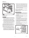
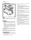
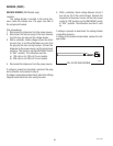
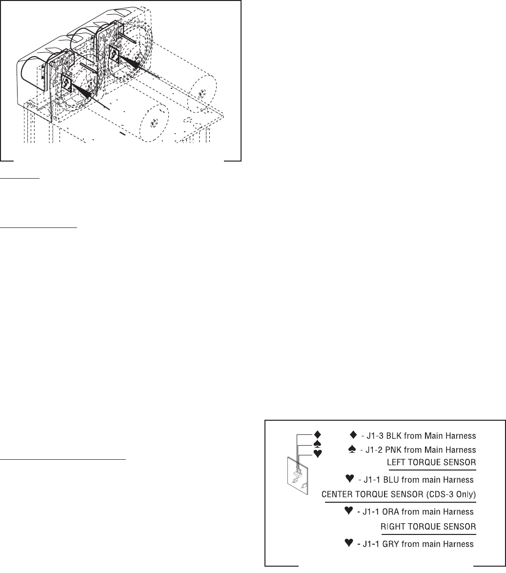
FIG. 49 TORQUE SENSOR CIRCUIT
BOARD TERMINALS
P1328
SERVICE (cont.)
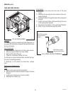
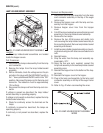
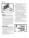
TORQUE SENSOR CIRCUIT BOARD
FIG. 48 TORQUE SENSOR CIRCUIT BOARD
P1341
Location:
The torque sensor circuit board is located on the
rear of the cooling drum mount just left of center.
Test Procedures:
1. With the ON/OFF switch and Auger switch in the
“ON” position and the ICE/OFF/NO-ICE switch in
the “ICE” position check the L.E.D. on the control
panel.
2. The L.E.D. for the torque sensor is located between
the appropriate auger switch and the ice switch.
3. If the L.E.D. flashes one time every four seconds
the auger is not turning. If the L.E.D. flashes three
times every four seconds the torque is less than
possible. If the L.E.D. flashes four times every four
seconds the torque is greater than possible.
4. If the L.E.D. flashes three times every four seconds,
four times every four seconds or one time every
four seconds with the auger turning, replace the
torque sensor circuit board.
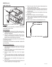
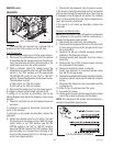
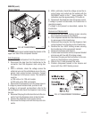
Removal and Replacement:
1. Remove the two #8-32 locking screws securing the
auger motor cover to the cooling drum mount.
2. Remove the cover and set aside for reassembly.
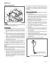
3. Remove the #8 locking screw on the lower right
side of the auger motor mounting bracket securing
the auger motor run capacitor. Set capacitor aside
with wires attached.
4. Disconnect the auger motor plug from the connector
on the main wiring harness.
5. Remove the three remaining #8 locking screws
securing the auger motor mounting bracket to
cooling drum mounting bracket.
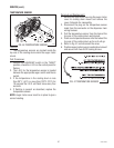
6. Remove motor with mounting bracket, drip tray,
split pin and torsion spring bearings as an assembly
and set aside for reassembly.
NOTE: When removing or installing the motor be sure
the split pin in the motor shaft is turned to a position
that will clear the torque sensor circuit board.
7. Disconnect the plug from the dispenser main wiring
harness to the torque sensor circuit board.
8. Remove the #8-32 locking screw and washer secur-
ing torque sensor circuit board to the cooling drum
mount.
9. Remove torque sensor circuit board and discard.
10. Install new torque sensor circuit board in the slot
in the rear of the cooling drum mount and secure
with a #8-32 locking screw and washer.
11. Refer to Fig. 49 and reconnect the wires.
12. Reinstall motor with mounting bracket, drip tray,
split pin and torsion spring bearings using three
#8 locking screws onto the cooling drum bracket.
13. Install the auger motor capacitor on the lower
right side of the auger mounting bracket using the
remaining #8 locking screw.
14. Connect the auger motor terminal to the terminal
on the main wiring harness.
15. Refer to Fig. 49 when reconnecting the wires.
16. Position the auger motor cover on the cooling
drum mount and secure with two #8-32 locking
screws.
27646 122200