


Page 14
SERVICE
This section provides procedures for testing and
replacing various major components used in this
brewer should service become necessary. Refer to
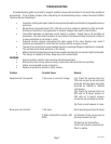
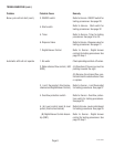
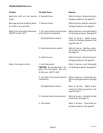
Troubleshooting
for assistance in determining the
cause of any problem.
WARNING - Inspection, testing, and repair of electri-
cal equipment should be performed only by qualified
service personnel. The brewer should be unplugged
when servicing, except when electrical tests are re-
quired and the test procedure specifically states to
plug in the brewer.
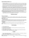
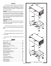
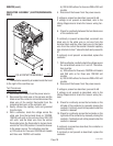
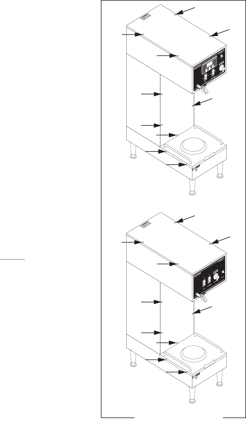
COMPONENT ACCESS
WARNING - Disconnect the brewer from the power
source before the removal of any panel or the replace-
ment of any component.
All components are accessible by the removal of
the top cover, front inspection panel and warmer base
plate.
The top cover is attached with four #6-32 screws.
The front inspection panel is attached with five
#6-32 screws.
The warmer base is attached with four #6-32
screws.
Contents
Brewer Selector Switch....................................... 16
Bypass Valve ...................................................... 15
Contactor Assembly............................................ 18
Control Thermostat............................................. 20
Digital Brewer Control (DBC) .............................. 22
Dispense Valve ................................................... 21
Level Control Board and Level Probe .................. 25
Limit Thermostat ................................................ 27
ON/OFF Switch (Warmer) ................................... 28
Overflow Protection Switch ................................ 29
Solenoid (Refill) .................................................. 30
Start Switch (Brew) ............................................32
Tank Heater ........................................................ 33
Timer (Early Models) .......................................... 34
Digital Timer (Late Models) ................................ 35
Triac/Heat Sink ................................................... 24
Warmer Element ................................................. 37
Wiring Diagrams................................................. 38
P1095.40
FIG. 1 COMPONENT ACCESS
27362 092900