


Page 21
DISPENSE VALVE
N
N
x
o
p
e
r
a
t
i
n
g
p
r
e
s
s
u
r
e
l
#
2
2
3
0
0
.
0
5
0
0
6
0
5
0
0
)
.
5
0
0
g
p
m
F
L
O
W
J2
S
ET
L
O
C
K
L
O
CK
SET
T
L
1
T
L
2
T
L
3
T
L
4
T
L
5
J
1
P2231.35
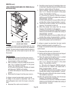
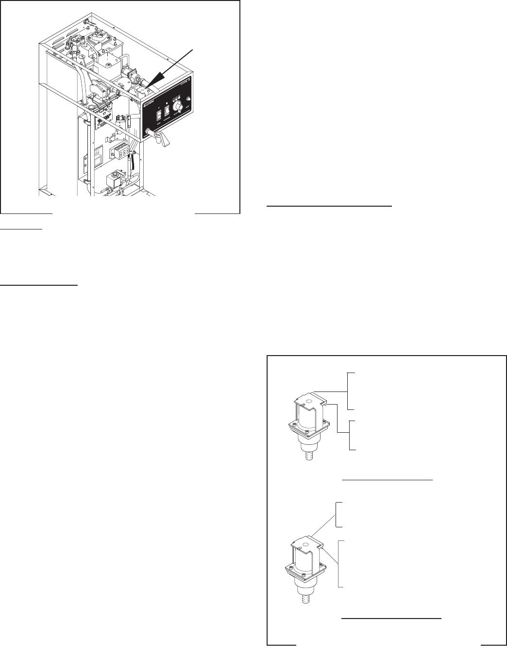
SERVICE (cont.)
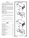
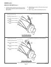
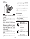
Location:
Dispense valve is located inside the hood directly
above the sprayhead.
Test Procedures:
1. Disconnect the brewer from the power source.
2. Disconnect the wires from the dispense valve and
check for continuity across the dispense valve coil
terminals.
If continuity is present as described, reconnect the
wires to the dispense valve and proceed to #3.
If continuity is not present as described, replace the
dispense valve.
3. With a voltmeter, check the voltage across dis-
pense valve using the white/violet wire and white/
green wire on electro/mechanical models, or white/
red wire and white/green wire on DBC models.
Connect brewer to the power source. Place the
"ON/OFF (Warmer)" switch in the "ON" (upper)
position. Press and release the start switch. The
indication must be:
a.) 120 volts ac for three wire 120/208 volt models
and three wire 120/240 volt models.
b.) 200 to 240 volts ac for two wire 200 or 240 volt
models.
4. Disconnect brewer from the power source.
If voltage is present as described in step 3, proceed to
#5.
If voltage is not present as described, refer to the
Wiring Diagrams
and check the brewer wiring har-
ness.
5. Check the dispense valve for coil action. Connect
the brewer to power source. Place the "ON/OFF
(Warmer)" switch in the "ON" (upper) position,
press and release the start switch. Listen carefully
in the vicinity of the dispense valve for a "clicking"
sound as the coil magnet attracts and repels the
plunger.
6. Disconnect the brewer from the power source.
If the sound is heard as described, there may be a
blockage in the dispense valve or the water line to the
dispense valve. Remove the dispense valve and in-
spect for wear, and remove waterborne particles.
If the sound is not heard as described, replace the
dispense valve.
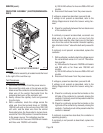
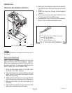
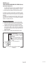
Removal and Replacement:
1. Disconnect wires from dispense valve.
2. Drain enough water from the tank so the dispense
valve is above the water line.
3. Remove water lines and hose barb fitting from
dispense valve.
4. Remove dispense valve from the sprayhead panel.
5. Install new dispense valve .
6. Reconnect the water lines, hose barb fitting and
the wires to the dispense valve.
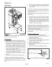
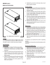
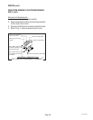
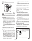
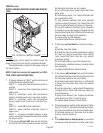
7. Refer to Fig. 11 when reconnecting wires.
P1106
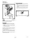
FIG. 10 DISPENSE VALVE
FIG. 11 DISPENSE VALVE TERMINALS
WHI/VIO to Timer TL1
WHI/VIO to ON/OFF Switch
WHI/RED to Brew Selector Switch
WHI/GRN to Timer TL4
WHI/GRN to By-Pass Valve
ELECTROMECHANICAL
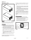
DIGITAL CONTROL (DBC)
WHI/GRN to Bypass Valve
WHI to DBC J1-3 (120/208 or 120/240 Volt
Models
RED to DBC J1-3 (200 or 240 Volt Models)
WHI/RED to DBC Board J1-2
WHI/RED to Brew Selector Switch
27362 092900