


Page 25
SERVICE (cont.)
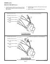
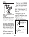
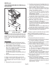
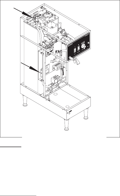
LEVEL CONTROL BOARD AND LEVEL PROBE (Electro/
mechanical only)
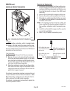
Location:
The level control board is located inside the front
of the brewer on the lower left side of the component
bracket. The level probe is located inside the hood on
the left center rear of the tank lid next to the limit
thermostat.
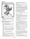
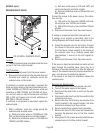
Test Procedure:
1. Disconnect the brewer from the power source.
2. Remove the violet wire from terminal 1 & pink wire
from terminal 4 of the circuit board.
3. With a voltmeter, check the voltage across termi-
nals 2 & 3. Connect the brewer to the power
source. The indication must be:
a.) 120 volts ac for three wire 120/208 volt models
and three wire 120/240 volt models.
b.) 200 to 240 volts ac for two wire 200 or 240 volt
models.
4. Disconnect the brewer from the power source.
If voltage is present as described, proceed to #5.
If voltage is not present as described, refer to the
Wiring Diagrams
and check the brewer wiring har-
ness.
5. Reconnect the violet wire to terminal 1.
B
U
N
N
9
0
p
s
i
g
m
a
x
op
e
r
a
tin
g
p
re
s
s
u
re
S
tra
in
e
r/F
l
o
w
C
o
n
tr
o
l
#
2
23
0
0
.
0
5
00
(R
e
p
l.
F
lo
w
W
a
s
h
e
r
#
2
0
5
2
6
.0
5
0
0
)
(R
e
p
l.
S
c
re
e
n
#
2
3
7
2
1
.0
0
0
0
)
.
5
0
0
g
p
m
F
L
O
W
!
C
A
U
T
I
O
N
H
O
T
W
A
T
E
R
J
2
S
ET
L
O
CK
L
OCK
S
E
T
T
L
1
T
L
2
T
L
3
T
L4
T
L
5
J
1
P2231.30
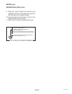
6. Carefully connect a piece of insulated jumper wire
to terminal 4. Keep the other end of this wire away
from any metal surface of the brewer.
7. With a voltmeter, check the voltage across termi-
nals 1 & 3. Connect the brewer to the power
source. The indication must be:
a.) 120 volts ac for three wire 120/208 volt models
and three wire 120/240 volt models after a delay of
approximately 1 second.
b.) 200 to 240 volts ac for two wire 200 or 240 volt
models after a delay of approximately 1 second.
8. Touch the free end of jumper wire to the brewer
housing. The indication must be 0.
9. Move the jumper wire away from the brewer
housing. The indication must again be:
a.)120 volts ac for three wire 120/208 volt models
and three wire 120/240 volt models after a delay of
approximately 1 second.
b.) 200 to 240 volts ac for two wire 200 or 240 volt
models after a delay of approximately 1 second.
10. Disconnect the brewer from the power source and
remove the jumper wire from terminal 4.
If voltage is present as described, the level control
board is operating properly, proceed to #11.
If voltage is not present as described, replace the level
control board.
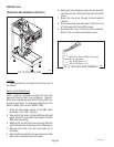
11. Reconnect the pink wire to terminal 4.
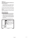
12. Gently pull the probe out of the tank lid and inspect
for corrosion. Replace it if necessary.
13. Place the probe so that neither end is in contact
with any metal surface of the brewer.
14. With a voltmeter, check the voltage across termi-
nals 1 & 3. Connect the brewer to the power
source. The indication must be:
a.) 120 volts ac for three wire 120/208 volt mod-
els and three wire 120/240 volt models after a
delay of approximately 1 second.
b.) 200 to 240 volts ac for two wire 200 or 240 volt
models after a delay of approximately 1 second.
15. Move the probe's flat end to the brewer housing.
The indication must be 0.
16. Move the probe's flat end away from the brewer
housing. The indication should be:
a.)120 volts ac for three wire 120/208 volt models
and three wire 120/240 volt models after a delay of
approximately 1 second.
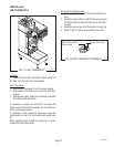
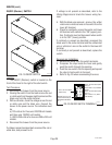
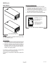
FIG. 15 LIQUID LEVEL CONTROL
BOARD AND PROBE
27362 092996