Page 20
SERVICE (cont.)
P1098
CONTROL THERMOSTAT (ELECTRO/MECHANICAL
ONLY)
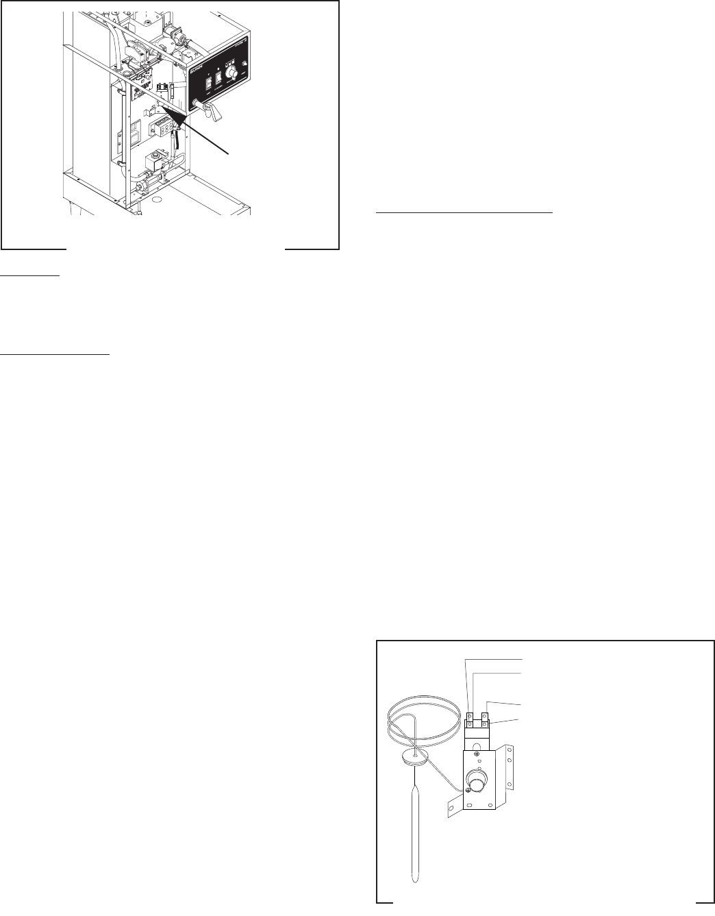
Location:
The control thermostat is located inside the front
of the brewer in the center of the component bracket.
Test Procedures:
1. Disconnect the brewer from the power source.
2. With a voltmeter, check the voltage across the blue
wires on the control thermostat and the white
insert on the three pole 120/208V, 120/240V ter-
minal block or the red insert on two pole 240V
terminal block. Connect the brewer to the power
source. The indication must be:
a.) 120 volts ac for three wire 120/208 volt models
and three wire 120/240 volt models.
b.) 200 to 240 volts ac for two wire 200 or 240 volt
models.
3. Disconnect the brewer from the power source.
If voltage is present as described, proceed to #4.
If voltage is not present as described, refer to the
Wiring Diagrams
and check the brewer wiring har-
ness.
4. Gently remove the capillary bulb and grommet
from the tank.
5. With a voltmeter, check the voltage across the
black wires of the control thermostat and the white
insert on the three pole 120/208V or 120/240V
terminal blocks and the red insert on two pole
200V/240V terminal blocks when the control ther-
mostat is turned "ON" (fully clockwise). Connect
the brewer to the power source. The indication
must be:
a.) 120 volts ac for three wire 120/208 volt models
and three wire 120/240 volt models.
B
U
N
N
9
0
p
s
i
g
m
a
x
o
p
e
r
a
t
i
n
g
p
r
e
s
s
u
r
e
S
t
r
a
i
n
e
r
/
F
l
o
w
C
o
n
t
r
o
l
#
2
2
3
0
0
.
0
5
0
0
(
R
e
p
l
.
F
l
o
w
W
a
s
h
e
r
#
2
0
5
2
6
.
0
5
0
0
)
(
R
e
p
l
.
S
c
r
e
e
n
#
2
3
7
2
1
.
0
0
0
0
)
.
5
0
0
g
p
m
F
L
O
W
J
2
S
E
T
L
O
C
K
L
O
CK
S
ET
T
L
1
T
L
2
T
L
3
T
L
4
T
L
5
J
1
P2231.30
b.) 200 to 240 volts ac for two wire 200 or 240 volt
models.
Voltage must not be indicated across these termi-
nals when the thermostat is turned "OFF" (fully
counterclockwise).
6. Disconnect the brewer from the power source.
If voltage is present as described, reinstall the capillary
tube into the tank to the line 7" above the bulb, the
control thermostat is operating properly.
If voltage is not present as described, replace the
thermostat.
Removal and Replacement:
1. Remove wires from the control thermostat.
2. Remove the thermostat capillary bulb by firmly
pulling up on the capillary tube on top of the tank
lid. This will disengage the grommet from tank lid.
3. Remove the #8-32 screw holding the control ther-
mostat to the component bracket.
4. Slide the grommet to the line 7" above the bulb on
the new capillary tube.
5. Insert the capillary bulb through the hole in the
tank lid and press the grommet firmly and evenly
so that the groove in the grommet fits into the tank
lid.
6. Carefully bend the capillary tube so that the tube
and bulb inside the tank are in the vertical position.
NOTE - The capillary tube must be clear of any electri-
cal termination and not kinked.
7. Using a #8-32 screw, fasten the control thermo-
stat to the component bracket.
8. Refer to Fig. 9 when reconnecting the wires.
9. Adjust the control thermostat as required.
FIG. 8 CONTROL THERMOSTAT
FIG. 9 CONTROL THERMOSTAT TERMINALS
BLU to Ready Light
BLU to RED Lead from Overflow
Protection Switch
BLK to BLK Lead on Contactor Coil
BLK to Ready Light
27362 092900


