


Page 30
SERVICE (cont.)
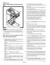
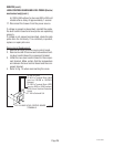
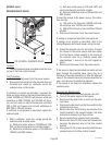
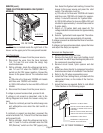
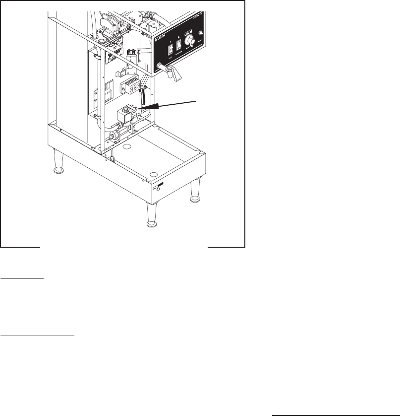
SOLENOID VALVE (Refill)
Location:
The inlet solenoid valve is located inside the trunk
on top of the flow control bracket.
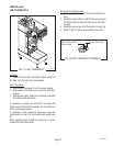
Test Procedure:
1. Disconnect the brewer from the power source.
2. Disconnect both wires from the solenoid valve coil
terminals and check for continuity across the
solenoid valve coil terminals.
If continuity is present as described, reconnect the
white and violet wires on the electro/mechanical con-
trolled 120/208 and 120/240 volt brewers, white and
white/blue on DBC 120/208 and 120/240 volt brew-
ers, red and violet on electro/mechanical controlled
200 or 240 volt brewers and red and white/blue on
DBC 200 or 240 volt brewers.
If continuity is not present as described, replace the
solenoid valve.
3. With a voltmeter, check the voltage across the
solenoid valve terminal wires:
a.) White and violet wires on 120/208 and 120/
240 volt electro/mechanical controlled models.
b.) White and white/blue wires on 120/208 and
120/240 volt DBC models.
B
U
N
N
9
0
p
s
i
g
m
a
x
o
p
e
r
a
t
i
n
g
p
r
e
s
s
u
r
e
S
t
r
a
i
n
e
r
/
F
l
o
w
C
o
n
t
r
o
l
#
2
2
3
0
0
.
0
5
0
0
(
R
e
p
l
.
F
l
o
w
W
a
s
h
e
r
#2
0
5
2
6
.
0
5
0
0
)
(
R
e
p
l
.
S
c
r
e
e
n
#
2
3
7
2
1
.
0
0
0
0
)
.
5
0
0
g
p
m
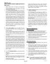
F
L
O
W
!
C
A
U
T
IO
N
H
O
T
W
A
T
E
R
J2
SE
T
L
O
C
K
L
O
CK
SET
T
L
1
T
L
2
T
L
3
T
L
4
T
L
5
J
1
P2231.35
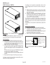
FIG. 23 REFILL SOLENOID VALVE
c.) Red and violet wires on 200 and 240V volt
electro/mechanical controlled models.
d.) Red and white/blue wires on 200 and 240 volt
DBC models.
Connect the brewer to the power source. The indica-
tion must be:
a.) 120 volts ac for three wire 120/208 volt mod-
els and three wire 120/240 volt models.
b.) 200 to 240 volts ac for two wire 200 or 240 volt
models.
4. Disconnect the brewer from the power source.
If voltage is present as described, proceed to #5.
If voltage is not present as described, refer to the
Wiring Diagrams
and check brewer wiring harness.
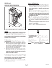
5. Check the solenoid valve for coil action. Connect
the brewer to the power source and draw water
from the faucet. Listen carefully in the vicinity of
the solenoid valve for a "clicking" sound after
approximately 1 second, as the coil magnet at-
tracts.
6. Disconnect the brewer from the power source.
If the sound is heard as described and water will not
pass through the solenoid valve, there may be a
blockage in the water line before or after the solenoid
valve or, the solenoid valve may require inspection for
wear, and removal of waterborne particles.
If the sound is not heard as described, replace the
solenoid valve.
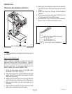
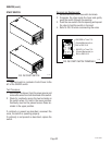
Removal and Replacement:
1. Remove all wires from the solenoid valve coil.
2. Turn off the water supply to the brewer.
3. Disconnect the water lines to and from the sole-
noid valve.
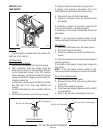
4. Disconnect water line from the flow control to the
solenoid and remove.
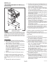
5. Remove the four #8-32 screws securing the flow
control bracket to the support bracket and slide
bracket and solenoid over flow control.
6. Remove bracket and solenoid as an assembly.
7. Remove the two #10-32 screws and lockwashers
securing the solenoid valve to the flow control
bracket.
8. Using two #10-32 screws securely install the new
solenoid valve to the flow control bracket.
27362 092900