


Page 34
SERVICE (cont.)
TIMER (ELECTRO/MECHANICAL ONLY)(EARLY
MODELS)
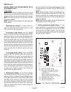
tion. Select the 2 gallon batch setting. Connect the
brewer to the power source and press the start
switch. The indication must be:
a.)120 volts ac for three wire 120/208 volt models
and three wire 120/240 volt models for approxi-
mately 1 minute 20 seconds for 2 gallon batch.
b.) 200 to 240 volts ac for two wire 200 or 240 volt
models for approximately 1 minute 20 seconds for
2 gallon batch.
7. Select a 1-1/2 gallon batch and repeat #6. The
voltage indication should remain for approximately
1 minute.
8. Select a 1 gallon batch and repeat #6. The indica-
tion should remain approximately 40 seconds.
If voltage is present as described the timer is function-
ing properly.
If voltage is not present as described, replace the timer
and adjust the dial(s) as required.
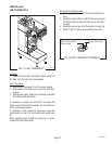
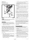
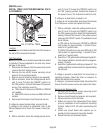
Removal and Replacement:
1. Remove all wires from the timer.
2. Remove the two #6-32 keps nuts holding circuit
board and two #8-32 keps holding dial plate on to
the component mounting bracket.
3. Remove circuit board, nylon spacers and dial
plate.
4. Install new timer directly to component mounting
bracket as described in
Late Model Timer
Section.
5. Refer to Fig. 32 when reconnecting wires.
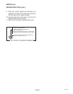
6. Install the Timer Setting Decal, provided with the
replacement timer, on the inside of the front ac-
cess panel.
7. Adjust the timer as required. Refer to
Late Model
Timer
Section on the following pages.
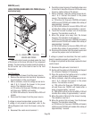
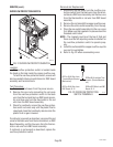
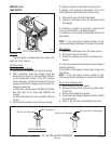
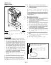
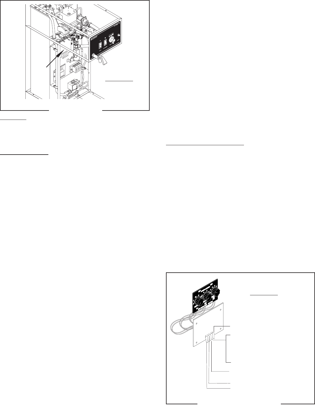
Location:
The timer is located inside the right front of the
brewer on the upper part of the component bracket.
Test Procedures:
1. Disconnect the brewer from the power source.
2. Disconnect the wires from the timer terminals
TL3, TL4 and TL5 and rotate the dial(s) fully
counterclockwise.
3. With a voltmeter, check the voltage across termi-
nals TL1 and TL2 when the "ON/OFF (Warmer)"
switch is in the "ON" (upper) position. Connect the
brewer to the power source. The indication must
be:
a.)120 volts ac for three wire 120/208 volt models
and three wire 120/240 volt models.
b.) 200 to 240 volts ac for two wire 200 or 240 volt
models.
4. Disconnect the brewer from the power source.
If voltage is present as described, proceed to #5.
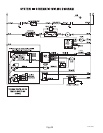
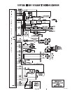
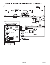
If voltage is not present as described, refer to the
Wiring Diagrams
and check the brewer wiring har-
ness.
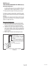
5. Check for continuity across the white/orange wire
and white/yellow wire when the start switch is
pressed.
If continuity is present as described, reconnect the
wires to terminals TL3, TL4 and TL5 of the timer board
and proceed to #6.
6. With a voltmeter, check the voltage across termi-
nals TL1 and TL4 with a voltmeter when the "ON/
OFF (Warmer)" switch is in the "ON" (upper) posi-
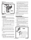
P1109
P1093
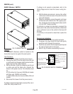
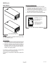
FIG. 29 TIMER
FIG. 30 TIMER TERMINALS
OLD STYLE
WHI/VIO TL1 to ON/OFF Switch
WHI TL2 to Terminal BLock (WHI Insert)
(120/208V or 120/240V Three Pole Ter-
minal Block)
RED TL2 to Terminal Block (RED Insert)
(200V or 240V Two Pole Terminal Block)
WHI/ORN TL3 to Start Swtich
WHI/GRN TL4 to Dispense Valve
WHI/YEL TL5 to Start Switch
OLD STYLE
27362 092900