


Page 33
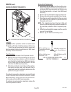
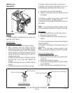
Location:
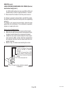
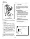
The tank heater is located inside the hood on the
right rear of the tank lid.
Test Procedure:
Electro/Mechanical Models.
1. Disconnect the brewer from the power supply.
2 With a voltmeter, check the voltage across the
black and the red wire on the tank heater. With the
control thermostat turned to the "ON" position
(fully clockwise), connect the brewer to the power
supply and check the voltage across the wires. The
indication should be:
a.) 208 volts ac for three wire 120/208 volt models
and 240 volts ac for three wire 120/240 volt
models.
b.) 200 to 240 volts ac for two wire 200 or 240 volt
models.
3. Disconnect the brewer from the power supply.
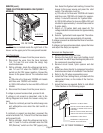
SERVICE (cont.)
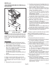
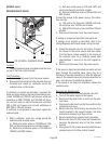
TANK HEATER
P837
J
2
SET
L
O
C
K
L
O
CK
SE
T
T
L
1
T
L
2
T
L
3
T
L
4
T
L
5
J
1
P2231.35
DBC
ELECTRO/MECHANICAL
FIG. 27 TANK HEATER
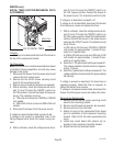
If voltage is present as described, proceed to #4.
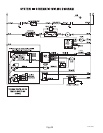
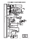
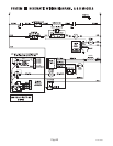
If voltage is not present as described, refer to the
Wiring Diagrams
and check the wiring harness.
4. Disconnect wires from the tank heater.
5. Check for continuity across the terminals of the
tank heater.
If continuity is present as described, reconnect the
wires, the tank heater is operating properly.
If continuity is not present as described, replace the
tank heater.
NOTE - If the tank heater remains unable to heat,
remove and inspect the heater for cracks in the sheath.
DBC Models:
1. Disconnect the brewer from the power source.
2. Disconnect wires from heater.
3. Check for continuity across the tank heater ter-
minals.
If continuity is present as described, the tank heater is
operating properly.
If continuity is not present as described, replace the
tank heater.
NOTE - If the tank heater remains unable to heat,
remove and inspect the heater for cracks in the sheath.
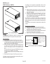
Removal and Replacement:
1. Remove wires from tank heater.
2. Remove the four #8-32 nuts securing tank heater
to tank lid.
3. Remove tank heater and gasket.
4. Install new tank heater and gasket with four #8-32
nuts on tank lid.
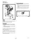
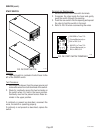
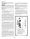
5. Refer to Fig. 28 when reconnecting the wires.
FIG. 28 TANK HEATER TERMINALS
BLU Lead from Triac Assembly
BLK to Limit Thermostat
RED to Contactor T1
BLK to Limit Thermostat
27362 092996