


Page 37
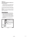
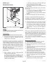
4. Disconnect wires from the warmer element.
5. Check the continuity across the two terminals on
the warmer element.
If continuity is present as described, reconnect the
white or red wire and white/red wires, or the white or
red wire and white/violet wires on the warmer element.
If continuity is not present as described, replace the
warmer element.
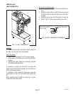
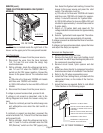
Removal and Replacement:
1. Remove the four #6-32 screws securing the base
(warmer) plate to the brewer housing.
2. Turn base plate over and disconnect the two wires
from the warmer element.
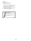
3. Remove the #8-32 Keps nut, warmer retainer plate
and warmer element. Discard warmer element.
4. Place new warmer element on the center bottom
of the base plate with the warmer terminals point-
ing up and to the rear of the base plate.
5. Install warmer retainer plate and warmer element
over the stud in bottom of the base plate, secure
with #8-32 Keps nut.
6. Reconnect the two wires to warmer element termi-
nals.
7. Turn base plate over and reinstall with four #6-32
screws to the brewer housing.
8. Refer to Fig. 34 when reconnecting wires.
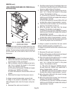
SERVICE (cont.)
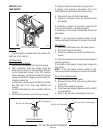
WARMER ELEMENT
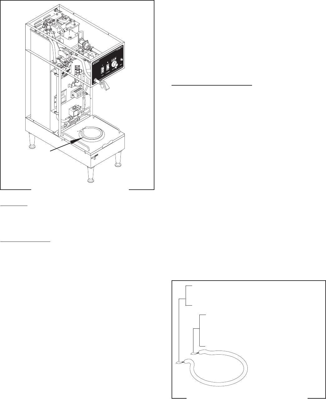
Location:
The warmer element is located on the bottom the
base (warmer) plate.
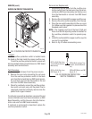
Test Procedures:
1. Disconnect the brewer from the power source.
2. On 120/208V or 120/240V models, with a voltme-
ter, check the voltage across the white wire and
the white/violet wire or white/red wire to the ele-
ment with the "ON/OFF (Warmer)" switch in the
"ON" (upper) position. On 200V or 240V models,
with a voltmeter, check the voltage across the red
wire and the white/violet wire or white/red wire
with the "ON/OFF (Warmer)" switch in the "ON"
(upper) position. The indication must be:
a.)120 volts ac for three wire 120/208 volt models
and three wire 120/240 volt models.
b.) 200 to 240 volts ac for two wire 200 or 240 volt
models.
3. Disconnect the brewer from the power source.
If voltage is present as described, proceed to #4.
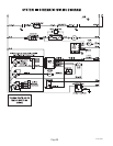
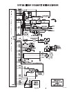
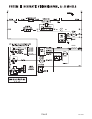
If voltage is not present as described, refer to the
Wiring Diagrams
and check brewer wiring harness.
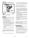
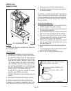
P1110
P1111.35
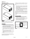
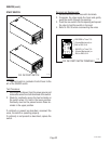
FIG. 33 WARMER ELEMENT
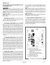
WHI/VIO to ON/OFF Switch (Electro/Mechanical)
WHI/RED to ON/OFF Switch (DBC)
WHI to Terminal Block (120/208V or 120/
240V Brewers)
RED to Terminal Block (200V or 240V
Brewers
FIG. 34 WARMER ELEMENT TERMINALS
27362 092996