


Page 16
5. Reattach the connector to the brew timer circuit
board or DBC connector.
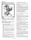
Grinder Interface:
6. Disconnect pink, gray and tan wires on the selector
switch from the pink, gray and tan wires on the
interface socket.
7. Check for continuity across the pink wire and the
tan wire on the selector switch when the switch is
in the 1 gallon position. Continuity must not be
present in any other position.
8. Check for continuity across the pink wire and gray
wire on the selector switch when the switch is in
the 1-1/2 gallon position. Continuity must not be
present in any other position.
9. Reconnect the pink, gray and tan wires on the
selector switch to the pink, gray and tan wires on
the interface socket.
Bypass Valve:
10. Disconnect the white/violet wire on the selector
switch from the bypass valve coil and disconnect
the white/red wire from the dispense valve coil.
11. Check for continuity across the white/violet wire
and white/red wire when the selector is in the 1-1/
2 gallon and 2 gallon position. Continuity must not
be present in any other position.
12. Reconnect the white/violet wire to the bypass
valve coil and the white/red wire to the dispense
valve coil.
If continuity is as described the switch is operating
properly.
If continuity is not present as described replace switch
assembly.
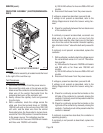
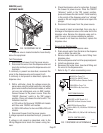
Removal and Replacement:
1. Disconnect the connector on the selector switch
harness from the brewer timer circuit board.
2. Disconnect wires from the selector switch, inter-
face socket, dispense valve and bypass valve.
3. Loosen the set screw on the switch knob.
4. Remove the 9/16" nut and washer holding the
switch to the hood.
5. Remove the switch.
6. Install the new switch. The positioning tab must be
in the hole in the hood for proper switch and knob
alignment.
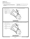
SERVICE (cont.)
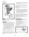
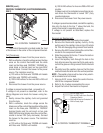
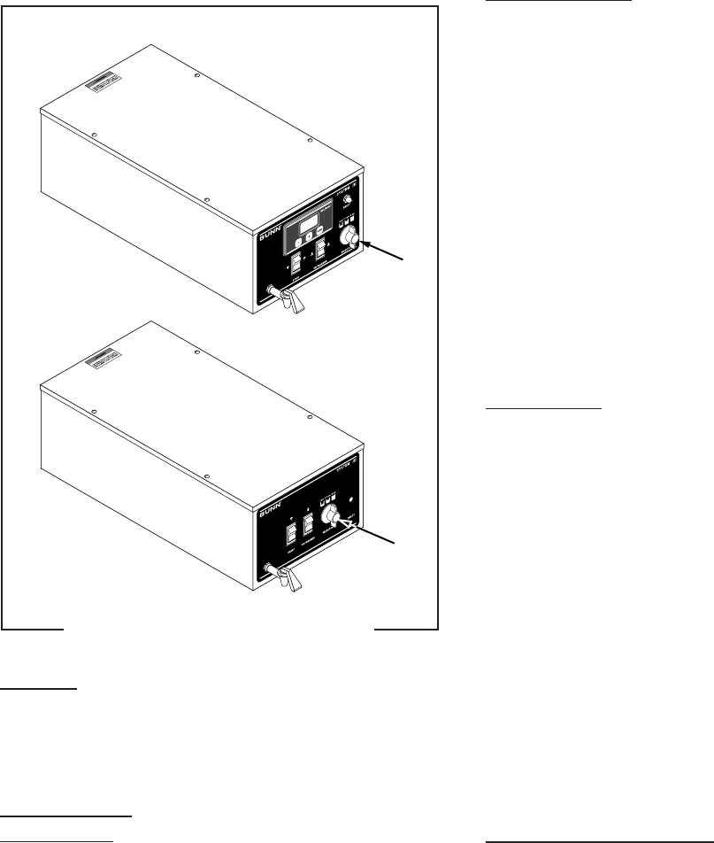
BREW SELECTOR SWITCH
Location:
The brew selector switch is located in the front of
the hood on the lower right side on DBC models and to
the right of center on electro/mechanical models.
Test Procedure:
Timer or DBC
1. Disconnect the brewer from the power supply.
2. Separate the connector on the selector switch
harness from the brew timer circuit board or DBC
connector.
3. Check for continuity across the pink and tan wires
on the connector when the switch is in the 1 gallon
position. Continuity must not be present in any
other position.
4. Check for continuity across the pink wire and the
gray wire when the switch is in the 1-1/2 gallon
position. Continuity must not be present in any
other switch position.
P1097.40
FIG. 4 BREW SELECTOR SWITCH
27362 092996