


13
Separate Machine Components — The design of
the 23XRV allows for disassembly at the job site so that
individual components may be moved through existing door-
ways. Use the following procedures to separate the machine
components.
Suggested locations to cut piping will minimize the width of
the condenser/economizer assembly.
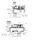
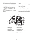
SEPARATE COOLER AND CONDENSER
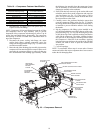
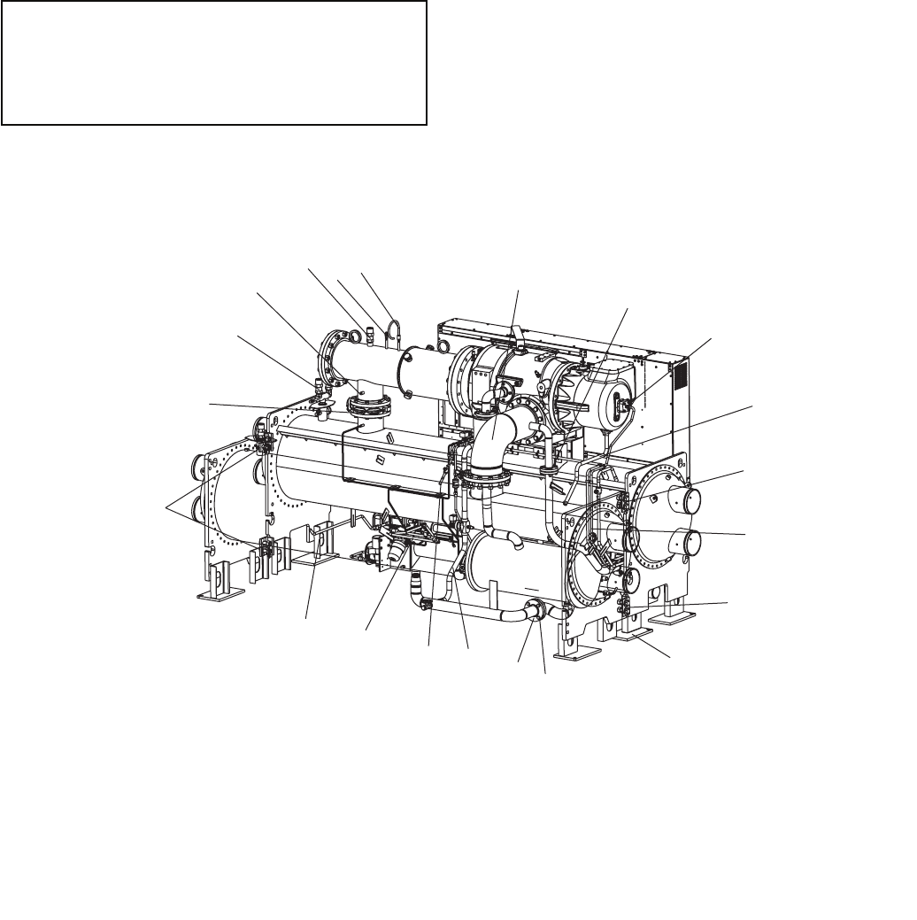
NOTE: For steps 1 through 13 refer to Fig. 12. The cooler has
been removed from the picture to show the pipes and lines that
must be cut.
Check that the holding charge has been removed from the
chiller.
1. Place a support plate under each tube sheet to keep each
vessel level.
2. Remove cooler relief valve and relief valve vent piping.
3. Cut the motor cooling refrigerant drain line.
4. Rig the suction elbow and disconnect the compressor
suction line at the cooler and compressor. Remove bolts
from the vaporizer vent line flange.
5. Cut the VFD cooling drain line.
6. Cut the oil reclaim line(s).
7. Cut the hot gas bypass line between the HGBP (hot gas
bypass) solenoid valve and the cooler feed line.
8. Unbolt the cooler liquid feed line near the economizer or
condenser float chamber at the flanged connection.
Temporarily secure the in-line economizer orifice plate
(economized chillers only) to the economizer flange (see
Fig. 12).
IMPORTANT: If the cooler and condenser vessels
must be separated, the heat exchangers should be kept
level by placing a support plate under the tube sheets.
The support plate will also help to keep the vessels
level and aligned when the vessels are bolted back
together.
19
18
17
16
15
14
5
13
12
11
10
9
8
7
5
6
5
4
3
2
1
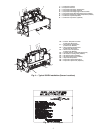
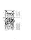
1—Suction Elbow (Unbolt) 11 — VFD Cooling Drain Line
2—Vaporizer Vent Line (Unbolt) 12 — Oil Reclaim Line (Cut)
3—Motor Cooling Line (Unbolt) 13 — Vaporizer Hot Gas Return Line (Cut)
4—Motor Cooling Drain Line (Cut) 14 — Discharge Isolation Valve (Optional)
5—Tubesheet Mounting Bracket 15 — Condenser Relief Valves (Unscrew)
6—Bearing Oil Drain Line 16 — Discharge Temperature Sensor
7—Support Plate 17 — Discharge Pipe Assembly Relief Valve (Unscrew)
8—In-Line Economizer Orifice Plate 18 — Discharge Pressure Sensor
9—Cooler Liquid Feed LIne (Unbolt) 19 — Discharge Pressure Switch
10 — Hot Gas Bypass Line (Cut)
Fig. 12 — Cooler/Discharge Pipe Assembly Removal
a23-1560