


43
COMPLETING THE INSTALLATION
This section provides instructions on how to perform a final
check of the installation. Do not energize the VFD circuit
breaker. This should only be done by qualified Carrier person-
nel in accordance with the 23XRV Start-Up and Service
Manual.
Checking the Installation — Use the following pro-
cedure to verify the condition of the installation:
1. Turn off, lock out, and tag the input power to the drive.
Wait five minutes.
2. Verify that there is no voltage at the input terminals (L1,
L2, and L3) of the power module.
3. Verify that the status LEDs on the DPI Communications
Interface Board are not lit. See Fig. 48. The location of
the Communications Interface Board is shown in Fig. 6.
4. Remove any debris, such as metal shavings, from the
enclosure.
5. Check that there is adequate clearance around the
machine in accordance with the certified print.
6. Verify that the wiring to the terminal strip and the AC
input power terminals is correct.
7. Check that the wire size is within terminal specifications
and that the wires are tightened properly.
8. Check that specified branch circuit protection is installed
and correctly rated.
9. Check that the incoming power is rated correctly.
10. Verify that a properly-sized ground wire is installed and a
suitable earth ground is used. Check for and eliminate any
grounds between the power leads. Verify that all ground
leads are unbroken.
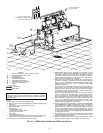
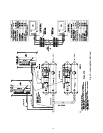
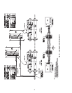
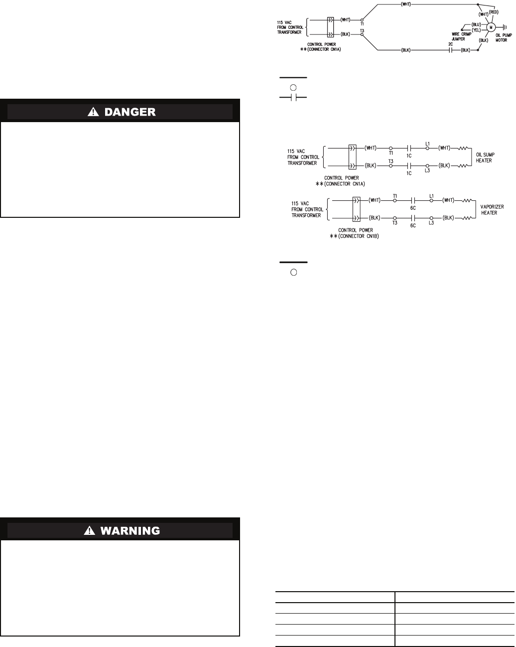
Oil Pump and Oil Heater — The oil pump and oil
heater are wired at the factory. It is not necessary to connect
additional wiring to these components. See Fig. 51 and 52.
Connect Control Wiring — All control wiring must
use shielded cable. Refer to the job wiring diagrams for cable
type and cable number. Make sure the control circuit is ground-
ed in accordance with applicable electrical codes and instruc-
tions on machine control wiring label.
Carrier Comfort Network
®
Interface — The Car-
rier Comfort Network (CCN) communication bus wiring is
supplied and installed by the electrical contractor. It consists of
shielded, 3-conductor cable with drain wire.
The system elements are connected to the communication
bus in a daisy chain arrangement. The positive pin of each
system element communication connector must be wired to the
positive pins of the system element on either side of it. The
negative pins must be wired to the negative pins. The signal
ground pins must be wired to the signal ground pins. See
Fig. 49 for location of the CCN network connections on the
terminal strip labelled CCN.
NOTE: Conductors and drain wire must be 20 AWG (Ameri-
can Wire Gage) minimum stranded, tinned copper. Individual
conductors must be insulated with PVC, PVC/nylon, vinyl,
Teflon, or polyethylene. An aluminum/polyester 100% foil
shield and an outer jacket of PVC, PVC/nylon, chrome vinyl,
or Teflon with a minimum operating temperature range of –4 F
to 140 F (–20 C to 60 C) is required. See Table 13 for cables
that meet the requirements.
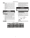
Table 13 — Cable Manufacturers
DC bus capacitors in the VFD retain hazardous voltages
after input power has been disconnected. After disconnect-
ing input power, wait 5 minutes for the DC bus capacitors
to discharge then check both the VFD DPI Communica-
tions Interface Board Status LEDs and the VFD with a
voltmeter to ensure the DC bus capacitors are discharged
before touching any internal components. Failure to
observe this precaution could result in severe bodily injury
or loss of life.
Voltage to terminals T1 and T3 on the 1C and 6C contac-
tors comes from a control transformer in the starter built to
Carrier specifications. Do not connect an outside source of
control power to the chiller (terminals T1 and T3). An
outside power source will produce dangerous voltage at the
line side of the starter, because supplying voltage at the
transformer secondary terminals produces input level
voltage at the transformer primary terminals (see Fig. 46,
51, and 52).
MANUFACTURER CABLE NO.
Alpha 2413 or 5463
American A22503
Belden 8772
Columbia 02525
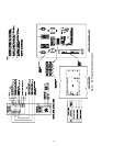
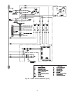
LEGEND
Factory Wiring
Power Panel Component Terminal
Contactor
Fig. 51 — Oil Pump Wiring
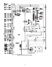
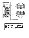
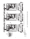
Fig. 52 — Oil Heater and Control Power Wiring
LEGEND
Factory Wiring
Power Panel Component Terminal
a23-1595
a23-1596