


35
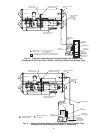
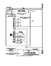
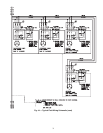
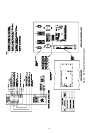
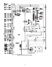
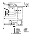
NOTES FOR FIG. 44
GENERAL
1.0 Variable frequency drive (VFD) shall be designed and
manufactured in accordance with Carrier engineering
requirements.
1.1 All field-supplied conductors, devices and the field-
installation wiring, termination of conductors and devices,
must be in compliance with all applicable codes and job
specifications.
1.2 The routing of field-installed conduit and conductors and the
location of field-installed devices, must not interfere with
equipment access or the reading, adjusting or servicing of
any component.
1.3 Equipment installation and all starting and control devices,
must comply with details in equipment submittal drawings
and literature.
1.4 Contacts and switches are shown in the position they would
assume with the circuit de-energized and the chiller
shutdown.
1.5
POWER WIRING TO VFD
2.0 Provide a means of disconnecting branch feeder power to
VFD. Provide short circuit protection and interrupt capacity
for branch feeder in compliance with all applicable codes.
2.1 If metal conduit is used for the power wires, the last 4 feet or
greater should be flexible to avoid transmitting unit vibration
into the power lines and to aid in serviceability.
2.2 Line side power conductor rating must meet VFD nameplate
voltage and chiller minimum circuit ampacity.
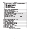
2.3 Lug adapters may be required if installation conditions
dictate that conductors be sized beyond the minimum
ampacity required. Circuit breaker lugs will accommodate
the quantity (#) and size cables (per phase) as shown in
Table 12.
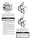
2.4 Compressor motor and controls must be grounded by using
equipment grounding lug provided inside unit mounted VFD
enclosure.
CONTROL WIRING
3.0 Field-supplied control conductors to be at least 18 AWG or
larger.
3.1 Ice build start/terminate device contacts, remote start/stop
device contacts and spare safety device contacts, (devices
not supplied by Carrier), must have 24 VAC rating. Max cur-
rent is 60 mA, nominal current is 10 mA. Switches with gold
plated bifurcated contacts are recommended.
3.2 Remove jumper wire between TB1-19 and TB1-20 before
connecting auxiliary safeties between these terminals.
3.3 Each integrated contact output can control loads (VA) for
evaporator pump, condenser pump, tower fan low, tower fan
high, and alarm annunciator devices rated 5 amps at
115 VAC and up to 3 amps at 277 VAC.
Do not use control transformers in the control center as the
power source for external or field-supplied contactor coils,
actuator motors or any other loads.
3.4 Do not route control wiring carrying 30 V or less within a
conduit or tray which has wires carrying 50 V or higher or
along side wires carrying 50 V or higher.
3.5 Spare 4-20 mA output signal is designed for controllers with
a non-grounded 4-20 mA input signal and a maximum input
impedance of 500 ohms.
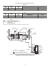
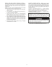
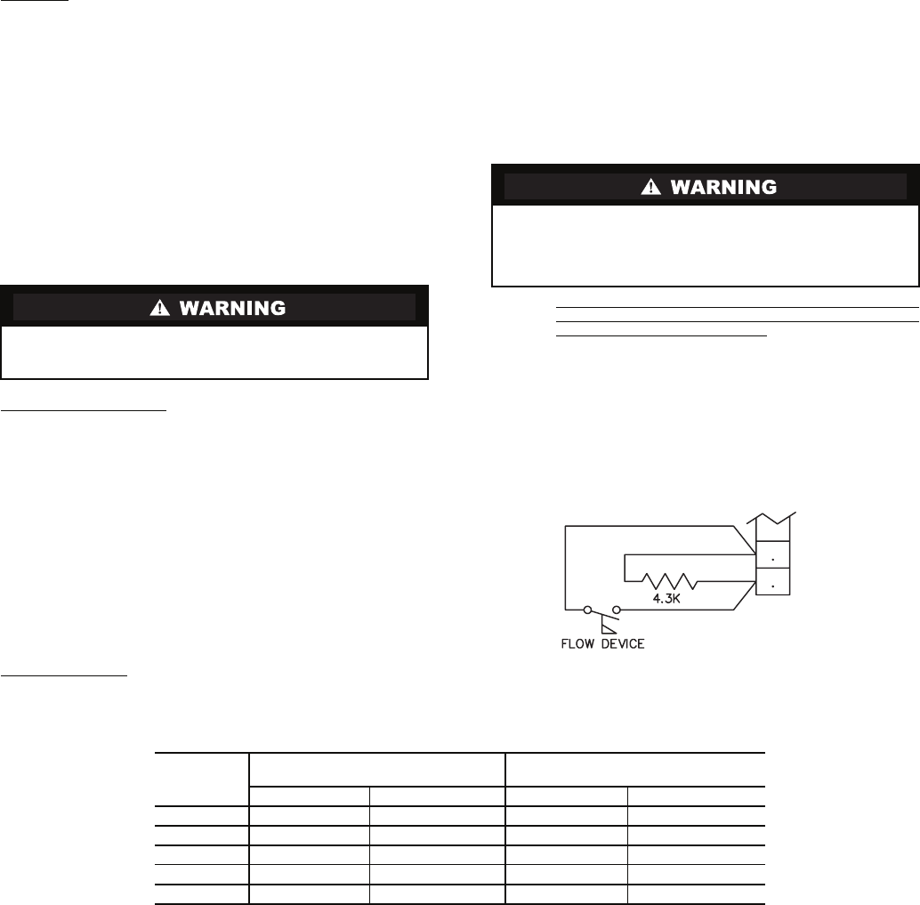
3.6 Flow devices to confirm evaporator or condenser pump flow
are not required. However; if flow devices are used, wire as
shown on drawing 23XRC1-1 (J3 lower). Remove jumper
installed at these terminals and wire in a 4.3 K resistor in its
place.
The flow device and resistor must be installed in parallel at
these terminals such that the resistor provides a signal when
the flow device is open.
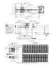
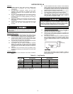
Table 12 — Lug Capacity
NOTE: If larger lugs are required, they can be purchased from the manufacturer of the circuit
breaker (Cutler-Hammer or Square D).
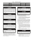
Do not use aluminum conductors. Contractor/installer assumes all
liability resulting from the use of aluminum conductors within the
VFD enclosure.
Control wiring required for Carrier to start pumps and tower fan
motors and establish flows must be provided to assure machine
protection. If primary pump, tower fan and flow control is by other
means, also provide a parallel means for control by Carrier. Failure
to do so could result in machine freeze-up or over-pressure.
CCM
J3 (LOWER)
a23-1587
VFD
MAX. INPUT
AMPS.
STANDARD 65K AIC LUG CAPACITY
(PER PHASE)
OPTIONAL 100K AIC LUG CAPACITY
(PER PHASE)
No. Conductors Conductor Range No. Conductors Conductor Range
225A 3 3/0 — 500MCM 2 3/0 — 250MCM
338A 3 3/0 — 500MCM 2 400 — 500MCM
440A 3 3/0 — 500MCM 2 400 — 500MCM
520A 3 3/0 — 500MCM 3 3/0 — 400MCM
608A 3 3/0 — 500MCM 3 3/0 — 400MCM