


15
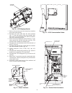
3. Remove the nuts that secure the terminal box transition
piece to the motor housing.
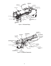
4. Disconnect the motor leads from the motor terminals
(Fig. 17). Note the position of the motor terminal cable
lugs so they can be reinstalled with sufficient clearance
away from surrounding structure.
5. Remove the motor temperature sensor leads (Fig. 17), the
motor ground lead, and the bolts that secure the VFD
enclosure to the terminal box transition piece.
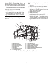
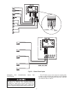
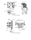
6. Disconnect the communication cables from the back of
the ICVC (Fig. 18).
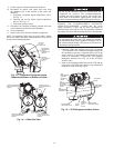
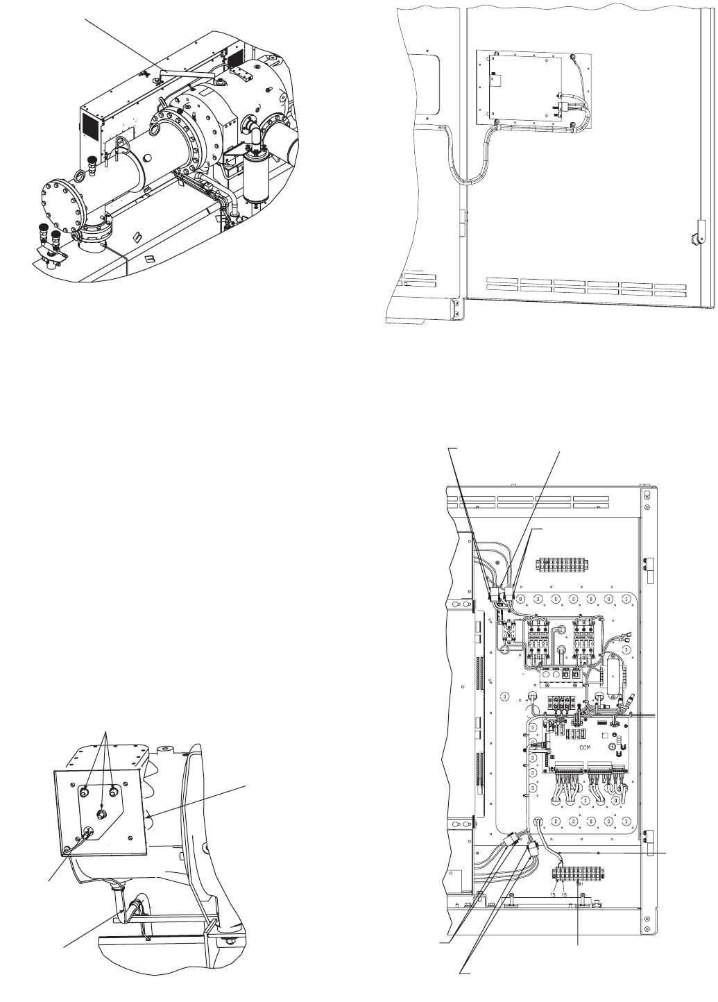
7. Disconnect the high pressure switch leads from terminal
strip TB1, terminals 15 and 16 (Fig. 19).
8. Unplug connectors CN1A, CN1B, CN2, and CN3
(Fig. 19).
9. Disconnect the control panel ground wire (Fig. 19) that is
located next to connectors CN1A and CN1B.
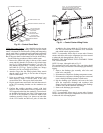
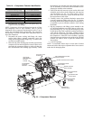
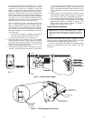
10. Disconnect the VFD cooling lines (Fig. 20) and cover all
openings.
11. Remove the 12 screws that secure the control panel to the
VFD enclosure. Tilt the control panel away from the back
of the control center.
12. Position the control panel on top of the condenser and
secure it in place to prevent damage.
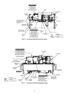
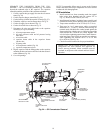
SHIPPING
BRACKET
Fig. 16 — VFD Shipping Bracket
a23-1565
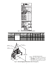
MOTOR TERMINAL
BOX FRAME
MOTOR
TEMPERATURE
CABLE
MOTOR
TEMPERATURE
SENSOR TERMINAL
BLOCK
MOTOR TERMINALS
Fig. 17 — Motor Terminals
a23-1566
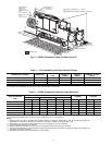
Fig. 18 — ICVC Communication Cables
a23-1567
CONNECTOR CN1A
CONNECTOR CN1B
CONTROL PANEL
GROUND WIRE
CONNECTOR
CN2
CONNECTOR CN3
LOW VOLTAGE FIELD
WIRING TERMINAL STRIP
HIGH
PRESSURE
SWITCH
CABLE
Fig. 19 — Control Panel Connectors
a23-1570