


14
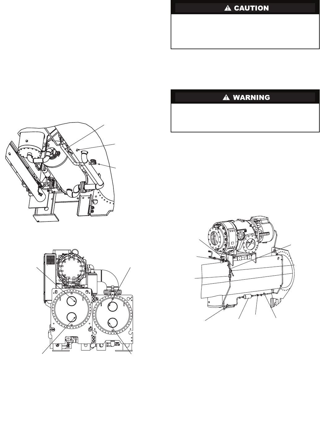
9. Cut the vaporizer refrigerant return line as shown.
10. Disconnect all sensors with cables that cross from
the condenser side of the machine to the cooler side
including:
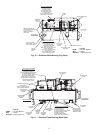
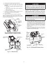
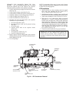
a. Evaporator refrigerant liquid temperature sensor.
See Fig. 13.
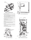
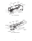
b. Entering and leaving chiller liquid temperature
sensors. See Fig. 14.
c. Evaporator pressure sensor.
11. Disconnect the tubesheet mounting brackets from the
vessel connectors on the tube cooler tubesheet.
12. Cover all openings.
13. Rig the cooler away from the condenser/compressor.
NOTE: To reassemble, follow steps in reverse order. Connect
sensors and cables after major components have been secured
to reduce the risk damaging them.
REMOVE THE CONTROLS/DRIVE ENCLOSURE
FROM THE CONDENSER — Confirm that the power
supply disconnect is open and all safety procedures are
observed before removing the VFD. This procedure minimizes
the number of sensors and cables that need to be disconnected.
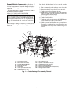
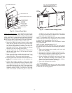
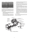
1. Close the 2 filter drier isolation valves (Fig. 15) and the
2 VFD isolation valves. Isolate the refrigerant charge into
the condenser to prevent a refrigerant leak if one of the
motor terminals is accidentally damaged during VFD
removal or installation. Evacuate the VFD coldplate
through the Schrader valve (Fig. 15) on the VFD drain
isolation valve.
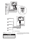
2. Remove the shipping bracket between the VFD and the
compressor if it is still in place. Remove any conduits that
bring power to the VFD. See Fig. 16.
Do not rig the condenser before the control center and
compressor are removed. The condenser/compressor
assembly has a high center of gravity and may tip over
when lifted at the tubesheet rigging points, which could
result in equipment damage and/or serious personal injury.
Do not attempt to remove the VFD without first isolating
the refrigerant charge in the condenser. Damage to one of
the motor terminals during VFD removal will result in an
uncontrolled refrigerant leak.
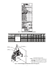
OPTIONAL
HOT GAS
BYPASS LINE
EVAPORATOR
REFRIGERANT
LIQUID
TEMPERATURE
SENSOR
COOLER
REFRIGERANT
PUMPOUT
VALVE
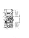
Fig. 13 — Evaporator Refrigerant Liquid
Temperature Sensor on Bottom of Cooler
LEAVING CHILLED
LIQUID TEMPERATURE
SENSOR
ENTERING CHILLED
LIQUID TEMPERATURE
SENSOR
ENTERING CONDENSER
LIQUID TEMPERATURE
SENSOR
LEAVING CONDENSER
LIQUID TEMPERATURE
SENSOR
Fig. 14 — Chiller End View
a23-1563
a23-1635
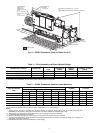
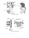
VFD
REFRIGERANT
COOLING
SOLENOID
VALVE
VFD
REFRIGERANT
COOLING
ISOLATION
VALVE
VFD
REFRIGERANT
STRAINER
FILTER DRIER
ISOLATION VALVE
FILTER
DRIER
MOTOR
COOLING
SIGHT
GLASS
FILTER DRIER
ISOLATION VALVE
SCHRADER
VALVE
VFD DRAIN
ISOLATION
VALVE
Fig. 15 — VFD Refrigerant Isolation Valves
a23-1564