6
4
31
8
61
71
81
9
1
1
2
3
7
6
6
5
21
11
51
6
1
8
9
01
41
8
21
02
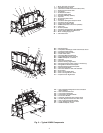
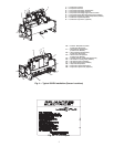
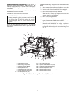
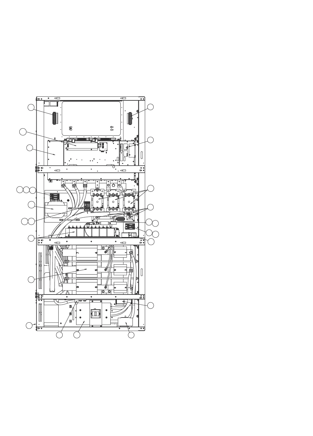
Fig. 6 — Control Center Components
1—Input Inductor Assembly 12 — Fuse, Class CC, 600V, 1A (3)
2—Capacitor Bank Assembly 13 — Transformer, 3kVA
3—Pre-Charge Resistor Assembly 14 — Line Sync PC Board Assembly
4—AC Contactor (3) 15 — Line Sync Board Cover
5—Power Module Assembly 16 — Fan, 115V (3)
6—Terminal Block, 10-Position (2) 17 — Circuit Breaker, 600V, 15A
7—Power Module Nameplate 18 — Circuit Breaker, 600V
8—Fuse Black, 30A, 600V, Class CC 19 — Lug, Ground, 2-600 MCM
9—Fuse, Class CC, 600V, 15A (2) 20 — Communications Interface Board
10 — Fuse, Class CC, 600V, 5A (1) 21 — Input Power Wiring Panel
11 — Fuse, Class CC, 600V, 20A (3)
a23-1554


