


19
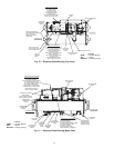
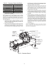
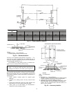
SEPARATE THE VAPORIZER FROM THE CON-
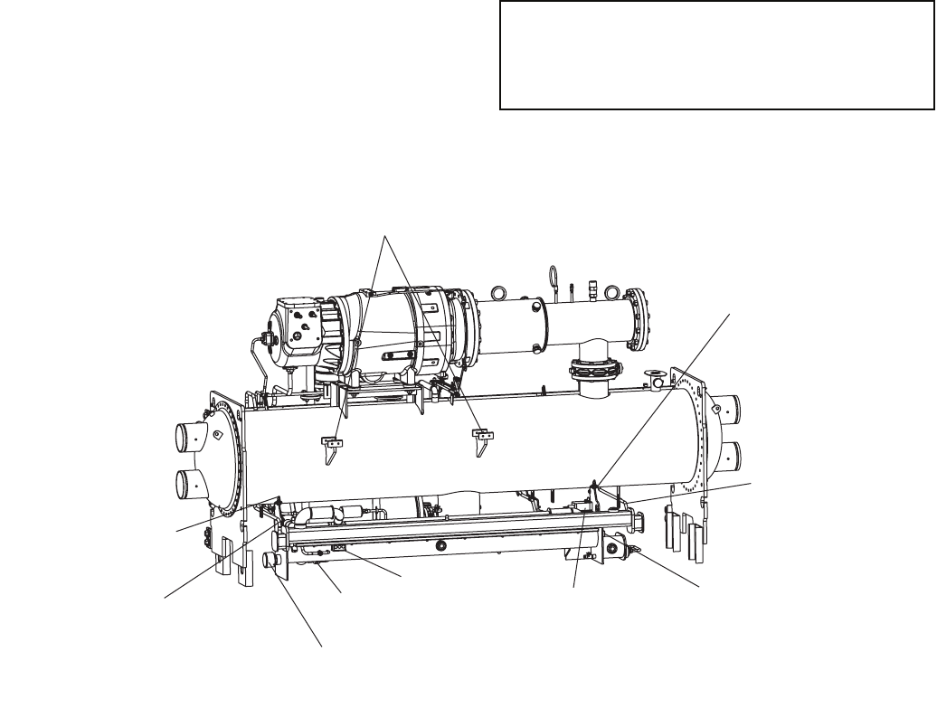
DENSER — The VFD mounting brackets (Fig. 24) extend
beyond the outboard edge of the vaporizer. The vaporizer
extends beyond the perimeter of the condenser tubesheet.
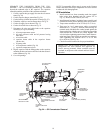
1. Cut the vaporizer hot gas supply line near the oil concen-
trator (Fig. 24).
2. Cut the vaporizer hot gas return line (Fig. 24).
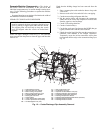
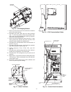
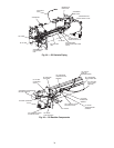
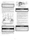
3. Cut the bearing oil drain line near the oil sump (Fig. 25).
4. Unbolt the vaporizer vent line flange shown in Fig. 25.
5. Cut the oil supply line as shown in Fig. 25.
6. Cut the oil reclaim line as shown in Fig. 25.
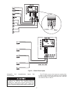
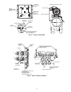
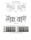
7. Disconnect all wires and cable leads to the vaporizer
assembly (see Fig 26) including:
a. oil sump temperature sensor
b. oil sump pressure cable and oil pressure leaving
filter cable
c. oil reclaim cable
d. vaporizer heater cable in the vaporizer heater
junction box
e. oil pump cable
f. oil sump heater conduit (Fig. 24)
g. vaporizer temperature sensor
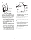
8. Rig the vaporizer with the lifting points on the vaporizer
mounting bracket and remove the four bolts that secure it
to the condenser (Fig. 24).
9. Cover all openings.
NOTE: To reassemble, follow steps in reverse order. Connect
sensors and cables after major components have been secured
to reduce the risk damaging them.
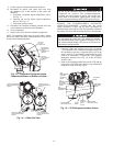
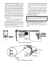
VFD Installation
1. Install terminal box frame mounting studs into tapped
holes using short threaded end (see section E-E in
Fig. 27). Do not exceed 120 ft-lb (163 N-m).
2. Install thermal insulators, insulation frame assembly, and
terminal box frame prior to attaching motor power cables.
3. Torque motor terminals to 45 to 55 ft-lb (61 to 75 N-m).
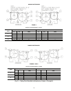
4. There may be 1 or 2 motor power cables per terminal
identified as T1, T2 and T3. Position motor end lugs on
terminal studs with Belleville washer located against the
front terminal lug with the convex side facing toward the
front terminal nut. Clinch the two cables together with
wire ties before tightening terminal nuts. Install front ter-
minal nut finger tight. Hold front terminal nut stationary
while tightening rear terminal nut to 45 to 50 ft-lb
(61 to 68 N-m). (See Fig. 28.)
5. Check all terminal connections for proper installation.
IMPORTANT: Do not insulate terminals until wiring
arrangement has been checked and approved by
Carrier start-up personnel. Motor terminals must be
insulated in acceptance with national and local electri-
cal codes.
VFD MOUNTING
BRACKETS
VAPORIZER
MOUNTING
BOLTS
VAPORIZER HOT
GAS SUPPLY LINE
OIL SUMP
HEATER JUNCTION
BOX
OIL PRESSURE
REGULATOR ISOLATION
VALVE
VAPORIZER HEATER
JUNCTION BOX
OIL RECLAIM
ACTUATOR
OIL PUMP
JUNCTION BOX (HIDDEN)
VAPORIZER
REFRIGERANT
RETURN LINE
VAPORIZER
MOUNTING
BOLTS
Fig. 24 — Oil Concentrator Removal
a23-1573