3
Identifying the Drive by Part Number
— Each LiquiFlo™
2.0 AC drive can be identified by its part number. See Fig. 5.
This number appears on the shipping label and on the VFD
nameplate.
Drive Input Component Location
— Figure 6 identifies the
control center components.
Identifying the Power Module by I.D. Number
— Each Liqui-
Flo 2.0 AC power module can be identified by its I.D. number.
See Fig. 5. This number appears on the shipping label and on the
power module’s nameplate. Power ratings are provided in
Table 1.
INSTALLATION REQUIREMENTS — Certain requirements
should be checked before continuing with the chiller’s electri-
cal installation. Input power wire sizes, branch circuit protec-
tion, and control wiring are all areas that need to be evaluated.
Determining Wire Size Requirements
— Wire size should be
determined based on the size of the conduit openings, and
applicable local, national, and international codes (e.g., NEC
[National Electric Code]/CEC [California Energy Commis-
sion] regulations). General recommendations are included in
the Carrier field wiring drawing.
Conduit Entry Size
— It is important to determine the size of
the conduit openings in the enclosure power entry plate so that
the wire planned for a specific entry point will fit through the
opening. Do NOT punch holes or drill into the top surface of
the control center enclosure for field wiring. Do not punch
holes or drill into the top surface of the control center enclosure
for field wiring. Knockouts are provided in the back of the
control center for field control wiring connections.
Recommended Control and Signal Wire Sizes
— The rec-
ommended minimum size wire to connect I/O signals to the
control terminal blocks is 18 AWG (American Wire Gage).
Recommended terminal tightening torque is 7 to 9 in.-lb
(0.79 to 1.02 N-m).
Recommended Air Flow Clearances
— Be sure there is ade-
quate clearance for air circulation around the enclosure.
A 6-in. (152.4 mm) minimum clearance is required wherever
vents are located in the VFD enclosure.
Match Power Module Input and Supply Power Ratings
— It
is important to verify that building power will meet the input
power requirements of the Machine Electrical Data nameplate
input power rating. Be sure the input power to the chiller
corresponds to the chiller’s nameplate voltage, current, and fre-
quency. Refer to machine nameplate in Fig. 7. The machine
electrical data nameplate is located on the right side of the
control center.
PROVIDE MACHINE PROTECTION — Protect machine
and VFD enclosure from construction dirt and moisture. Keep
protective shipping covers in place until machine is ready for
installation.
If machine is exposed to freezing temperatures after water
circuits have been installed, open waterbox drains and remove
all water from cooler and condenser. Leave drains open until
system is filled.
It is important to properly plan before installing a 23XRV
unit to ensure that the environment and operating conditions
are satisfactory. The installation must comply with all require-
ments in the certified prints.
Rigging the Machine — The 23XRV machine can be
rigged as an entire assembly. Large interconnecting piping has
flanged connections that allow the compressor, cooler, and
condenser sections to be separated and rigged individually. In
addition, the VFD can be removed and rigged separately.
RIG MACHINE ASSEMBLY — See rigging instructions on
label attached to machine. Also refer to rigging guide (Fig. 8),
physical data in Fig. 9, and Tables 2-9B. Lift machine only from
the points indicated in rigging guide. Each lifting cable or
chain must be capable of supporting the entire weight of the
machine.
Lifting machine from points other than those specified may
result in serious damage to the unit and personal injury.
Rigging equipment and procedures must be adequate for
machine weight. See Fig. 8 for machine weights.
NOTE: These weights are broken down into component
sections for use when installing the unit in sections. For the
complete machine weight, add all component sections and
refrigerant charge together. See Tables 5-9B for machine
component weights.
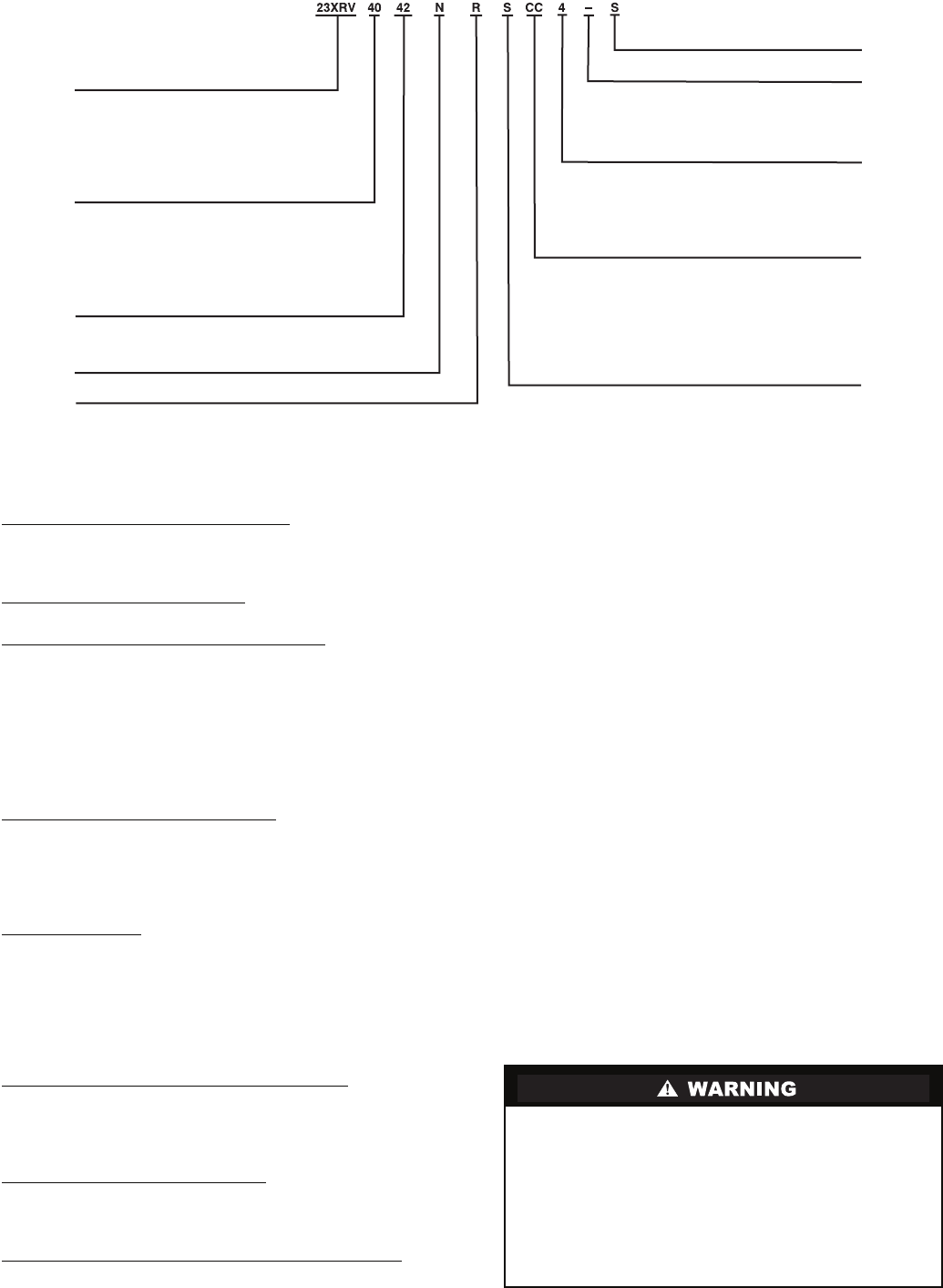
23XRV – High Efficiency
Variable Speed Screw Chiller
Cooler Size*
30-32
35-37
40-42
45-47
50-52
55-57
Condenser Size*
30-32
35-37
40-42
45-47
50-52
55-57
Economizer Option
E – With Economizer
N – No Economizer
S – Special
R – Compressor
Not Used
Voltage Code
3 – 380-3-60
4 – 416-3-60
5 – 460-3-60
9 – 400-3-50
Drive
Frame
AA
BA
BB
CC
Rectifier Max
Input Amps†
440
520
520
608
Inverter Max
Output Amps†
442
442
520
608
Motor Code
P
Q
R
S
T
U
V
Max Motor Amps
265
283
306
334
368
421
440
Fig. 2 — Model Number Identification
a23-1533
*First number denotes frame size.
†Maximum limits only. Additional application limits apply that may reduce these ampacities.


