


42
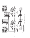
TO CHILLED WATER PUMP
TO CONDENSER WATER PUMP
TO COOLING TOWER FAN
TO
COOLING
TO W ER
FROM
COOLING
TO W ER
FROM
LOAD
TO
LOAD
3
5
4
DRAIN
MAIN COMPRESSOR
MOTOR POWER
1
1
1
1
2
SEE NOTE 4
6
7
8
9
9
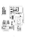
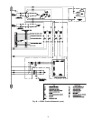
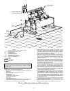
LEGEND
1—Disconnect (Fused on VFD only) NOT by Carrier
2—Unit Mounted VFD/Control Center
3—Pressure Gages
4—Chilled Water Pump
5—Condenser Water Pump
6 — Chilled Water Pump Starter
7 — Condensing Water Pump Starter
8 — Cooling Tower Fan Starter
9 — Vents
Piping
Control Wiring
Power Wiring
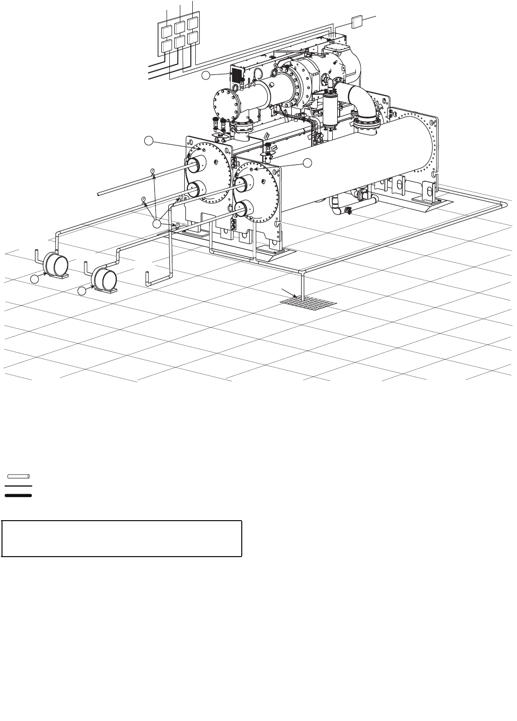
6. Field-installed piping must be arranged and supported to avoid
stress on the equipment and transmission of vibrations from the
equipment as well as to prevent interference with routine access for
the reading, adjusting and servicing of the equipment. Provisions
shall be made for adjustment in each plane of the piping and for
periodic and major servicing of the equipment.
7. Relief valves on the cooler and condenser must be vented to the
outdoors as discharging refrigerant in closed spaces may displace
oxygen and cause asphyxiation. All field-supplied refrigerant relief
piping and devices must be used in accordance with ANSI/
ASHRAE standard 15.
Dual pressure relief valves are mounted on the three-way valves in
some locations to allow testing and repair without transferring the
refrigerant charge. Three-way valve shafts should be turned either
fully clockwise or fully counterclockwise so only one relief valve is
exposed to refrigerant pressure at a time.
The flow area of discharge piping routed from more than one relief
valve, or more than one heat exchanger, must be greater than the
sum of the outlet areas of all relief valves that are expected to dis-
charge simultaneously. All relief valves within a machinery room
that are exposed to refrigerant may discharge simultaneously in the
event of a fire. Discharge piping should lead to the point of final
release as directly as possible with consideration of pressure drop
in all sections downstream of the relief valves.
8. Service access should be provided per standards ANSI/ASHRAE
15 and ANSI/NFPA 70 (NEC) and local safety codes. Unobstructed
space adequate for inspection, servicing and rigging of all major
components of the chiller is required. Shaded service areas are
shown on the certified machine assembly drawing plan view and
front view. See machine assembly component disassembly drawing
for component removal. Space for rigging equipment and compres-
sor removal is not shown.
9. The installation of chilled water and cooling tower water strainers
should be considered to prevent debris from collecting in the water-
boxes and degrading performance.
10. Flexible conduit should be used for the last few feet to the control
center for vibration isolation of power wiring and control wiring.
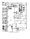
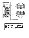
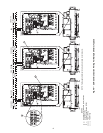
Fig. 50 — 23XRV with Unit-Mounted VFD/Control Center
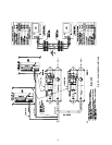
NOTES:
1. All wiring must comply with applicable codes.
2. Refer to Carrier System Design Manual for details regarding piping
techniques.
3. Wiring not shown for optional devices such as:
• remote start-stop
• remote alarm
• optional safety device
• 4 to 20 mA (1 to 5 VDC) resets
• optional remote sensors
• kW output
• head pressure reference
4. Service clearance under the chiller can be enhanced if the grout is
not extended along the entire length of the heat exchangers.
5. Carrier does not recommend pre-fab water piping.
IMPORTANT: Wiring and piping shown are for general point-of-
connection only and are not intended to show details for a specific
installation. Certified field wiring and dimensional diagrams are avail-
able on request.
a23-1594