


7
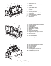
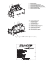
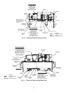
CHAIN “B”
(SEE NOTE #2)
CHAIN “C”
(SEE NOTE #2)
CHAIN “D”
(SEE NOTE #2)
15´-0´´
MIN. HEIGHT
ABOVE FLOOR
“E”
“F”
“A”
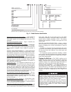
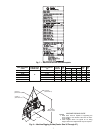
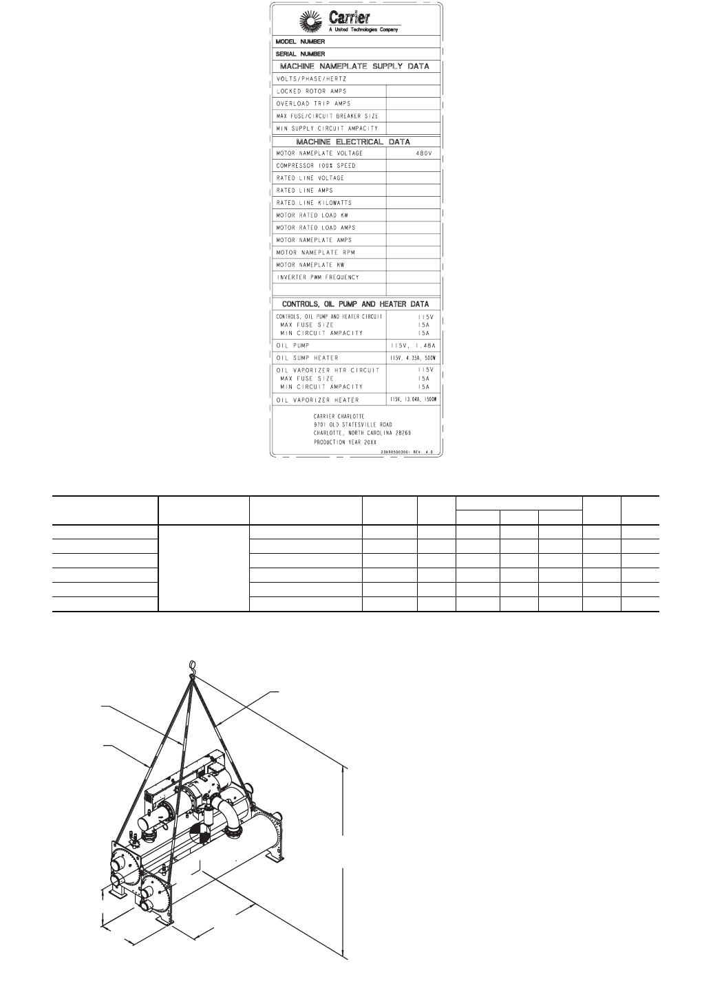
Fig. 7 — Machine Electrical Data Nameplate
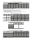
*The 11th character of the chiller model number indicates the frame size of the compressor.
HEAT EXHANGER
CODE
COMPRESSOR
FRAME SIZE*
MAXIMUM WEIGHT
(lb)
VESSEL
LENGTH
DIM.
“A”
CHAIN LENGTH
DIM.
“E”
DIM.
“F”
“B” “C” “D”
30-32
R
19,18712′ 6′-10″ 13′-5″ 13′-0″ 12′-5″ 3′-11″ 3′- 8″
35-37 20,58914′ 7′- 8″ 13′-10″ 13′-5″ 12′-10″ 3′-11″ 3′- 8″
40-42 23,928 12′ 6′-10″ 13′-6″ 12′-8″ 12′-3″ 4′-1″ 3′-11″
45-47 25,167 14′ 7′- 8″ 13′-11″ 13′-2″ 12′- 8″ 4′-1″ 3′-11″
50-52 26,950 12′ 6′-10″ 13′-10″ 12′-7″ 12′-9″ 4′-0″ 4′-4″
55-57 28,479 14′ 7′- 8″ 14′-4″ 13′-1″ 13′-1″ 4′-0″ 4′-4″
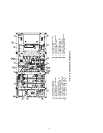
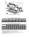
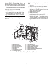
MACHINE RIGGING GUIDE
NOTES:
1. Each chain must be capable of supporting the
entire weight of the machine. See chart for maxi-
mum weights.
2. Chain lengths shown are typical for 15′ lifting
height. Some minor adjustments may be required.
Fig. 8 — Machine Rigging Guide (Cooler Size 30 Through 57)
a23-1555
a23-1556